Additive Manufacturing of Metals: Laser PBF, DED, and Binder Jetting
Metal additive manufacturing (AM) encompasses a family of layer-by-layer fabrication processes that build near-net-shape components directly from digital models by depositing and consolidating metallic material — powder, wire, or slurry — using a focused heat source or binder. This article provides a technically rigorous treatment of the three commercially dominant metal AM process families — laser powder bed fusion (L-PBF), directed energy deposition (DED), and binder jetting — covering process physics, solidification and solid-state transformations, defect formation mechanisms, post-processing requirements, and alloy-specific behaviour relevant to structural applications in aerospace, energy, and biomedical sectors.
Key Takeaways
- L-PBF achieves the highest resolution and geometric complexity but induces severe residual stress and strong crystallographic texture along the build direction.
- Rapid solidification in L-PBF (105–107 K/s) suppresses equilibrium phase formation and produces fine, metastable microstructures requiring post-processing heat treatment.
- Lack-of-fusion and keyhole porosity arise from opposite ends of the energy density spectrum and require different corrective actions.
- DED enables repair and large-format fabrication with wire or powder feedstock, at lower spatial resolution but greater deposition rates than L-PBF.
- Binder jetting avoids in-process thermal stress entirely but requires sintering, which introduces 15–20% shrinkage and limits achievable density without HIP.
- Hot isostatic pressing (HIP) is the single most effective post-processing step for closing internal porosity and recovering fatigue performance in fusion-based AM parts.
Process Physics of Laser Powder Bed Fusion (L-PBF)
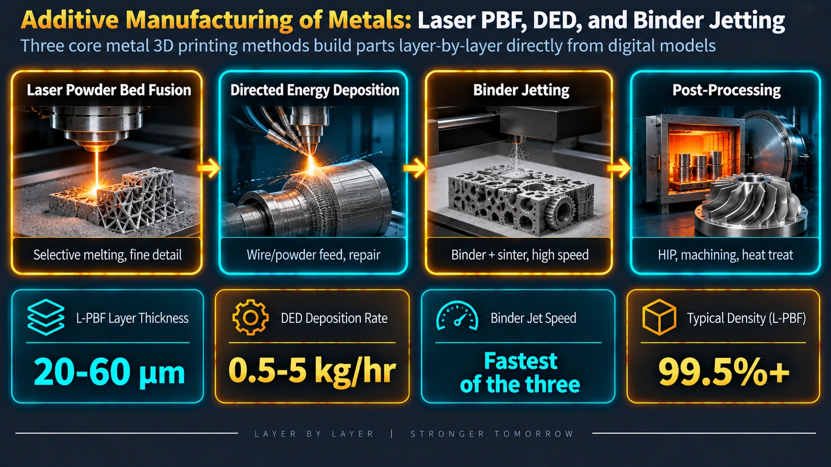
L-PBF — marketed under trade names including Selective Laser Melting (SLM), Direct Metal Laser Sintering (DMLS), and LaserCUSING — is currently the most widely deployed metal AM process for producing complex, near-net-shape parts in stainless steels, nickel superalloys, titanium alloys, and cobalt-chrome. A focused single-mode fibre laser (typically 200–500 W, 1064 nm, Gaussian TEM00 mode) rasters across a powder bed contained within a build chamber flooded with Ar or N2 to suppress oxidation. The laser selectively melts tracks of metallic powder (D50 typically 20–45 µm) in accordance with the cross-sectional geometry of each layer; the build platform descends by one layer thickness (20–60 µm), fresh powder is spread by a recoater blade, and the process repeats until the full component is consolidated.
Melt Pool Dynamics and Heat Transfer
The governing dimensionless parameters for L-PBF melt pool behaviour are the Peclet number (Pe) and the ratio of temperature gradient G to solidification velocity R, which determines the solidification mode. The volumetric energy density Ev provides a first-order process descriptor:
E_v = P / (v · h · t)

where:
  P = laser power (W)
  v = scan speed (mm/s)
  h = hatch spacing (mm)
  t = layer thickness (mm)
  E_v units: J/mm³

Typical target range: 50–100 J/mm³ (material-dependent)

Conduction mode melting: melt pool depth/width ratio < 1.5
Keyhole mode: depth/width ratio > 1.5 → vapour cavity instability
Within the melt pool, Marangoni convection — driven by the strong surface tension gradient dσ/dT (typically −0.3 to −0.5 mN/m/K for metallic melts) — drives fluid from the hot pool centre toward the cooler periphery, enhancing convective heat transfer and flattening the melt pool profile. This convective motion also stirs oxide films and promotes homogeneous composition distribution within each track.
Solidification Conditions and Microstructure
Solidification in L-PBF is characterised by an extreme combination of high temperature gradient G (106–107 K/m) and moderate solidification velocity R (0.05–0.5 m/s), placing most alloys firmly in the fully cellular or columnar dendritic regime on the G–R solidification mode map. The solidification microstructure scale is characterised by the primary dendrite arm spacing (PDAS):
PDAS = A · (G · R)^(-n)

For nickel alloys: A ≈ 50–80, n ≈ 0.25–0.33
Typical L-PBF PDAS: 0.3–2 µm (vs 5–50 µm for casting)

Cooling rate ε ≈ G · R ≈ 10^5–10^7 K/s
The steep thermal gradient forces grain growth along the maximum heat-flux direction (build direction, Z). Grains with their fastest-growth crystallographic direction — ⟨001⟩ for cubic systems such as austenitic steel, Inconel, and CoCr — aligned with Z out-compete misaligned neighbours through competitive growth, producing a strong {001}⟨001⟩ fibre texture. This texture is inherited across successive melt pools by epitaxial regrowth from previously solidified substrate, yielding columnar prior-beta grains in titanium alloys that can extend across tens of layers (millimetre-scale grain length).
Residual Stress Development
L-PBF generates the highest residual stresses of any metal AM process, governed by the temperature gradient mechanism (TGM). Each newly melted track is prevented from freely expanding by the surrounding cold material, inducing compressive plastic strain. On cooling, the contracted layer draws the surface into tension. Residual stress magnitudes at the part surface can approach the alloy yield strength (300–1000 MPa tensile at top surface, compressive at base).
Defect Formation in L-PBF
| Defect Type | Cause | Morphology | Ev Regime | Effect on Properties |
|---|---|---|---|---|
| Lack-of-fusion (LoF) | Insufficient energy density; incomplete interlayer bonding | Irregular, crack-like; unmelted powder inclusions | Low Ev (<50 J/mm³) | Severe fatigue life reduction; stress concentrators |
| Keyhole porosity | Excess energy density; vapour cavity collapse | Spherical, 50–200 µm; distributed | High Ev (>150 J/mm³) | Moderate fatigue effect; HIP-responsive |
| Gas porosity | Dissolved gas (N2, Ar) in powder; rapid solidification trapping | Fine spherical, <20 µm | Any | Minor (small size); not fully HIP-closed |
| Hot cracking | Solidification cracking or liquation cracking in HAZ | Intergranular, sharp | Any (alloy-specific) | Critical; fracture initiation sites |
| Balling | Poor wetting; Plateau–Rayleigh instability of melt track | Spherical beads; rough surface | Very high v or low P | Surface roughness; delamination risk |
| Delamination | Excessive residual stress during build | Inter-layer crack / layer separation | High stress alloys | Part failure during build or post-processing |
Directed Energy Deposition (DED)
DED encompasses processes that simultaneously deliver a heat source and feedstock material to a specific deposition point, building geometry by accumulating weld beads rather than melting a pre-spread powder bed. The heat source may be a laser (laser DED or laser metal deposition, LMD), electron beam (EBAM), or plasma/arc (wire arc additive manufacturing, WAAM). Feedstock may be blown powder (powder-fed DED) or wire (wire-fed DED). DED is particularly valuable for the repair of high-value components (turbine blades, dies, offshore drilling tools), for adding features to wrought substrates, and for producing large-format parts beyond the build volume of powder bed systems.
Process Parameters and Deposition Geometry
In powder-fed laser DED, powder is delivered coaxially or laterally through nozzles directed at the melt pool created by the laser on the substrate or previously deposited material. The powder catchment efficiency (fraction of delivered powder incorporated into the deposit) is typically 50–90%, varying with standoff distance, powder flow rate, and laser spot size. Key process parameters include:
Linear energy density (LED) = P / v   (J/mm)

Deposition rate (DR) = A_bead × v     (mm³/s)
  where A_bead = cross-sectional area of a single bead

Dilution ratio = (melted substrate area) / (total melt pool area)
  Typical target: 10–30% for repair applications
Compared to L-PBF, DED operates at significantly lower cooling rates (102–105 K/s), producing coarser dendritic microstructures with primary dendrite arm spacings of 5–30 µm — comparable to precision casting rather than wrought material. Repeated thermal cycling of previously deposited layers as new layers are added creates a complex, spatially varying heat treatment history within a single monolithic DED component, analogous to the multi-pass weld microstructure discussed in the HAZ microstructure article.
Wire Arc Additive Manufacturing (WAAM)
WAAM uses a gas metal arc (GMA), gas tungsten arc (GTA), or plasma arc as the heat source, with wire feedstock, to achieve deposition rates of 1–10 kg/h — one to two orders of magnitude higher than powder-bed processes. WAAM is most suited to large structural components in titanium (Ti-6Al-4V), aluminium (2319, 5356), nickel alloys, and high-strength steels where buy-to-fly ratio reduction drives commercial adoption. The as-deposited WAAM microstructure in Ti-6Al-4V consists of coarse columnar prior-beta grains (5–20 mm in length) with a Widmanstatten alpha-lath structure, similar to a slow-cooled casting. Post-deposition inter-pass rolling has been shown to break up columnar grains and introduce equiaxed, strain-refined microstructures with improved fatigue resistance.
Binder Jetting
Binder jetting separates the part-building stage completely from the densification stage. During printing, a printhead deposits liquid polymeric binder droplets (2–80 pL) onto thin layers of metallic powder (particle size D50 typically 5–35 µm, finer than L-PBF powder to maximise green-part density). No melting occurs at this stage; the binder bonds powder particles together by capillary and van der Waals forces. The resulting green part has a density of 55–65% and must subsequently be processed through debinding and sintering.
Debinding and Sintering
Thermal debinding burns off the polymeric binder in a controlled atmosphere (H2/N2 or Ar) at 300–600 °C, leaving an open-pore brown part of 55–60% theoretical density. Sintering at 0.8–0.98 Tm drives densification by surface diffusion, grain boundary diffusion, and viscous flow, targeting a final density of 95–99.5% theoretical. Residual porosity after sintering can be eliminated by post-sinter HIP.
Linear shrinkage S = (L_green - L_sintered) / L_green × 100%
  Typical range: 15–25% linear (45–60% volumetric)

Shrinkage must be compensated by scaling CAD model by factor k:
  k = 1 / (1 - S/100)

Example: 20% linear shrinkage → k = 1.25 (scale up by 25%)
Unlike fusion AM processes, binder jetting produces an equiaxed, thermally annealed microstructure after sintering, free of residual stress, columnar texture, and rapid-solidification metastable phases. This makes it well-suited to magnetically soft alloys (Fe-Si, Fe-Ni), cemented carbides (WC-Co), and complex copper components for heat exchangers, where the equiaxed grain structure and isotropic properties are desirable. Materials prone to oxidation (Al alloys) or with volatile alloying elements remain challenging due to the high sintering temperatures required.
Alloy-Specific Behaviour in Metal AM
Ti-6Al-4V
Ti-6Al-4V is the most widely processed alloy in L-PBF and DED. The beta transus Tβ is 995 ± 15 °C; L-PBF cooling rates from above Tβ are sufficient to form martensitic alpha prime (α’), which is a hexagonal phase supersaturated with vanadium. As-built L-PBF Ti-6Al-4V has:
| Condition | UTS (MPa) | YS (MPa) | Elongation (%) | Microstructure |
|---|---|---|---|---|
| As-built L-PBF | 1200–1270 | 1050–1150 | 4–8 | Martensitic α’ within columnar prior-β grains |
| Stress-relieved (650 °C / 2 h) | 1170–1250 | 1050–1130 | 5–9 | Decomposing α’ to α+β; stress reduced 40–60% |
| HIP (920 °C / 100 MPa / 2 h) | 930–980 | 850–920 | 13–17 | Equiaxed α+β; porosity eliminated |
| STA (900 °C WQ + 600 °C / 2 h) | 1100–1180 | 1000–1080 | 8–12 | Fine lamellar α+β; bimodal microstructure |
Inconel 718
Inconel 718 is the dominant nickel superalloy in metal AM for aerospace and energy applications. The alloy is precipitation-hardened by γ” (Ni3Nb, body-centred tetragonal, DO22) and γ’ (Ni3(Al,Ti), FCC, L12). In L-PBF, the rapid solidification suppresses niobium segregation to interdendritic regions but produces a significantly reduced γ” solvus width. Laves phase (Ni, Cr, Fe)2(Nb, Mo, Ti) — the primary embrittling phase in conventionally cast IN718 — is reduced in L-PBF compared to casting but not fully eliminated. The standard post-processing sequence per AMS 5664 (wrought) requires adaptation for AM:
L-PBF IN718 Post-Processing (typical aerospace practice):
1. Stress relief:         1065 °C / 1 h / AC  (above δ-phase solvus, ~1010 °C)
2. HIP:                   1163 °C / 100 MPa / 3 h / FC (closes porosity; dissolves Laves)
3. Solution anneal:       954 °C / 1 h / AC
4. Double ageing:         718 °C / 8 h / FC + 621 °C / 10 h / AC
Final hardness target:    ≥ 40 HRC; UTS ≥ 1380 MPa
316L Austenitic Stainless Steel
316L is one of the most extensively studied AM alloys due to its simple FCC microstructure and extensive industrial use. L-PBF 316L exhibits a hierarchical microstructure: columnar grains at the millimetre scale, cellular substructure at the 0.3–1 µm scale (boundaries decorated with dislocation networks and nano-oxide inclusions), and nano-scale segregation of Mo and Cr to cell walls. This cellular dislocation network provides a strengthening increment beyond the Hall–Petch contribution from grain size, giving as-built L-PBF 316L a yield strength of 500–570 MPa — significantly higher than wrought annealed material (200–250 MPa) — without sacrificing ductility. Annealing at 1050–1100 °C dissolves the cellular structure and recovers properties toward the wrought annealed condition.
Aluminium Alloys
Al alloys present specific challenges in L-PBF due to: high laser reflectivity at 1064 nm (requiring higher power densities); high thermal conductivity (rapid heat dissipation reducing melt pool stability); low viscosity (promoting spatter); and susceptibility to hot cracking. AlSi10Mg and AlSi12 (near-eutectic Al-Si alloys) are process-compatible due to their wide solidification range and minimal hot-crack susceptibility, producing a fine eutectic Si network within Al dendrites. High-strength wrought alloys (7xxx series: Al-Zn-Mg-Cu) are generally crack-prone in L-PBF; research into nano-particle grain refiners (ZrH2, TiB2 additions at 1–2 wt%) has demonstrated hot-crack suppression by promoting equiaxed nucleation ahead of the columnar front.
Post-Processing and Heat Treatment
The as-built microstructure from fusion-based metal AM — characterised by columnar texture, metastable phases, residual porosity, and high residual stress — rarely meets mechanical property requirements without post-processing. A systematic post-processing strategy is essential and must be specified in the process control plan before production.
Stress Relief
Stress relief is performed at sub-recrystallisation temperatures (typically 0.4–0.6 Tm) to reduce residual stress without significantly altering microstructure or hardness. For steels: 450–600 °C / 1–4 h. For titanium: 650 °C / 2 h in Ar. For Inconel 718: 1065 °C / 1 h (above delta-phase solvus). Parts must remain on the build plate during stress relief unless distortion analysis indicates acceptable dimensional change upon release.
Hot Isostatic Pressing (HIP)
HIP subjects the part to simultaneous high temperature (0.7–0.9 Tm, typically 900–1200 °C) and isostatic argon gas pressure (100–200 MPa) for 1–4 hours. Internal pores close by creep deformation and diffusional mass transport, improving fatigue life by 30–100% compared to as-built. HIP also partially recrystallises columnar grains (depending on temperature and strain energy), reduces texture intensity, and homogenises chemical segregation. Standard references: AMS 2801 for titanium HIP; AMS 7000 for nickel alloy HIP.
Surface Finishing
As-built surface roughness (Ra) in L-PBF is 5–25 µm depending on surface orientation relative to the laser (up-facing, down-facing, and side-skin surfaces differ substantially). Fatigue cracks nucleate preferentially from surface roughness peaks, making post-process machining, electropolishing, abrasive flow machining (AFM), or laser shock peening essential for fatigue-critical components. Down-skin surfaces (supported on powder below) are inherently rougher than up-skin surfaces and may require machining allowance in the CAD design.
Process Comparison: L-PBF, DED, and Binder Jetting
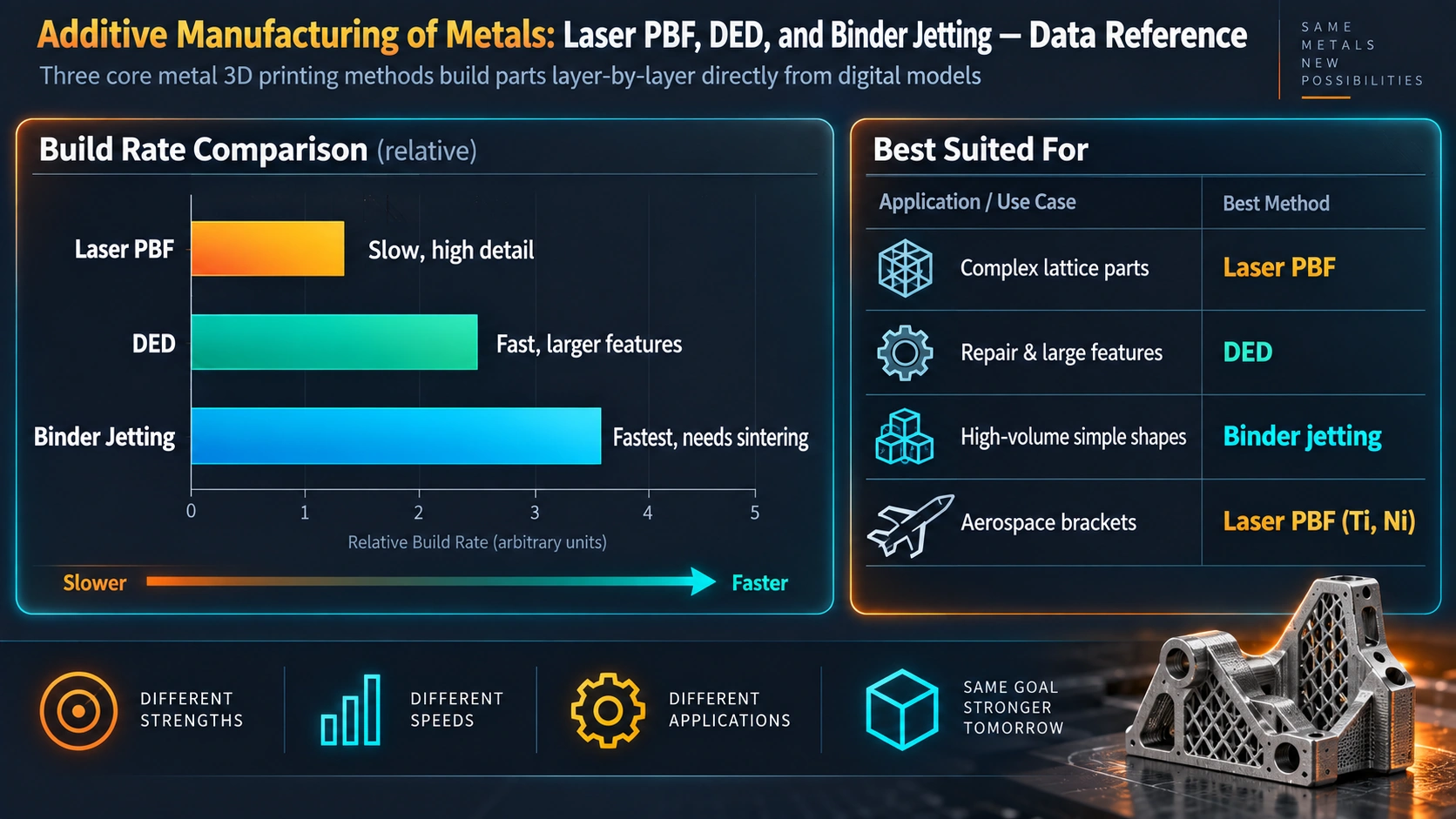
| Parameter | L-PBF | Laser DED (powder) | WAAM (wire arc) | Binder Jetting |
|---|---|---|---|---|
| Layer thickness | 20–60 µm | 200–1000 µm | 1–3 mm | 50–200 µm (green) |
| Deposition rate | 5–20 cm³/h | 10–200 cm³/h | 500–5000 cm³/h | High (no melting stage) |
| Spatial resolution | High (±50 µm) | Medium (±200 µm) | Low (±1 mm) | Medium (±100 µm) |
| As-built density | 99–99.9% | 98–99.8% | 99–99.9% | 55–65% (green); 95–99.5% (sintered) |
| Residual stress | Very high | Moderate | Low–moderate | Near-zero |
| Grain structure | Columnar, fine dendrites | Columnar, coarser dendrites | Coarse columnar, Widmanstätten | Equiaxed (post-sinter) |
| Max build size | 400 × 400 × 400 mm typical | Metres (CNC envelope) | Several metres | 400 × 500 × 400 mm typical |
| Best-suited alloys | SS, Ni, Ti, CoCr, tool steels | Ni, Ti, stellite, SS, refractory | Ti, Al, steel, Cu | SS, Cu, WC-Co, Fe-Si, IN625 |
| Primary application | Aerospace structures, implants, tooling | Repair, cladding, large parts | Large aerospace frames, naval | Complex small parts, magnetics |
Quality Assurance and Standards for Metal AM
Metal AM for structural applications requires a comprehensive quality management framework spanning powder supply, process qualification, in-process monitoring, non-destructive evaluation (NDE), and traceability. Relevant standards include:
ASTM / ISO Standards
- ISO/ASTM 52900: Terminology
- ISO/ASTM 52901: Purchased AM parts
- ASTM F3001: Ti-6Al-4V L-PBF
- ASTM F3049: Powder characterisation
- ASTM F2924: Ti L-PBF
Aerospace Standards
- AMS 7000: Ni alloy L-PBF
- AMS 7001: Ti-6Al-4V L-PBF
- AMS 7003: Ti-6Al-4V DED
- AMS 2801: Ti HIP
- AS9100 Rev D: QMS
NDE Requirements
- CT scanning: internal porosity (>50 µm)
- X-ray radiography: sub-surface flaws
- Ultrasonic testing: bulk defects
- FPI/MPI: surface cracks
- In-situ melt pool monitoring
Powder characterisation must be performed on each incoming batch: particle size distribution (laser diffraction, ASTM B822), apparent density and flowability (Hall flowmeter, ASTM B213), chemistry (ICP-OES, ASTM E1479), and oxygen/nitrogen content (inert-gas fusion, ASTM E1019). Oxygen pick-up in titanium powder above 0.2 wt% reduces ductility below aerospace specification limits.
Industrial Applications
Metal AM is transitioning from a rapid prototyping technique to a qualified production process in several high-value sectors. Understanding martensite formation in steel, bainite microstructure, and annealing and normalising principles provides the metallurgical basis for interpreting AM as-built and post-processed microstructures.
Aerospace
GE Aviation’s LEAP fuel nozzle — L-PBF from cobalt-chrome — consolidates 20 previously separate brazed components into a single part, reducing weight by 25% and increasing service life fivefold. CFM’s LEAP engine uses 19 fuel nozzle tips per engine, making this the highest-volume flight-qualified L-PBF application to date. Airbus uses L-PBF titanium brackets on the A350 XWB, with over 1000 flight-certified parts per aircraft.
Biomedical
Titanium (Ti-6Al-4V, Ti-6Al-7Nb) and CoCrMo lattice-structure implants — spinal cages, acetabular cups, tibial trays — are produced by L-PBF with tailored porosity (60–80% open pore volume, 300–600 µm pore size) designed to match cancellous bone stiffness and promote osseointegration. The hierarchical roughness of the as-built L-PBF surface promotes cell attachment without chemical surface treatment.
Oil and Gas / Energy
DED cladding and repair of Inconel 625 onto carbon steel substrates for corrosion protection (valves, flanges, nozzles) reduces costly replacement of entire components. WAAM is being evaluated for large pressure vessel nozzle fabrication, with qualification under ASME BPVC Section IX welding procedure principles adapted for DED deposition procedures.
Emerging Developments
Multi-material and functionally graded AM — achieved by simultaneously or sequentially altering feedstock composition in DED — enables spatially tailored properties (e.g., Ti-6Al-4V graded to Ti-Mo for reduced modulus at implant surfaces). Computational process optimisation using physics-based simulation (OpenFOAM melt pool CFD, finite element residual stress prediction) and machine learning surrogate models reduces experimental parameter development time from weeks to hours. In-situ monitoring by photodiode arrays, high-speed cameras, and pyrometry feeds real-time data into closed-loop control systems, detecting keyhole and LoF defect signatures and adjusting laser power within the same layer.
Understanding the grain boundary character and iron-carbon phase diagram fundamentals underpins interpretation of solid-state transformations during AM heat treatment. For related solidification science applicable to AM, see thermal spray coatings and laser DED cladding and repair.
Frequently Asked Questions
What is the difference between L-PBF and EBM in metal additive manufacturing?
Why do L-PBF parts exhibit strongly textured columnar grains?
What causes lack-of-fusion porosity in laser powder bed fusion?
What is keyhole porosity and how is it prevented?
How does directed energy deposition differ from powder bed fusion in terms of microstructure?
Why is hot isostatic pressing (HIP) commonly applied after metal AM?
Which alloy systems are best suited to additive manufacturing and why?
How does residual stress develop in L-PBF, and what are the mitigation strategies?
What post-processing heat treatments are required for L-PBF Ti-6Al-4V?
How is binder jetting different from fusion-based AM processes?
Recommended Reference Books
Additive Manufacturing of Metals — Herderick & Slotwinski (ASM)
Comprehensive coverage of metal AM processes, microstructure, properties, and qualification. Essential reference for practising engineers.
View on AmazonLaser Powder Bed Fusion of Polymers and Metals — Schmid
Detailed treatment of L-PBF process physics, powder properties, parameter optimisation, and machine engineering from a leading researcher.
View on AmazonFundamentals of Metal Casting — Flinn
Solidification fundamentals underpinning AM microstructure evolution: nucleation, dendrite growth, segregation, and defect formation.
View on AmazonMaterials Science and Engineering — Callister & Rethwisch
Graduate-level materials science foundation covering phase diagrams, diffusion, mechanical properties, and heat treatment relevant to AM post-processing.
View on AmazonDisclosure: MetallurgyZone participates in the Amazon Associates programme. If you purchase through these links, we may earn a small commission at no extra cost to you. This helps support free technical content on this site.
Further Reading
