Fibre Reinforced Metal Matrix Composites: Continuous Fibre Aluminium and Titanium Systems
Continuous fibre-reinforced metal matrix composites (MMC) combine the high axial stiffness and strength of ceramic fibres with the ductility, damage tolerance, and elevated-temperature capability of metallic matrices. The result is a class of structural materials that deliver specific stiffness and specific strength values unattainable by monolithic alloys, enabling weight-critical applications in aerospace propulsion, airframe structures, and space systems. This article covers the science and engineering of continuous fibre MMC with emphasis on the two most industrially significant systems: SiC monofilament in Ti-6Al-4V (Ti-MMC) and SiC or carbon fibre in aluminium alloys (Al-MMC).
Key Takeaways
- Continuous fibre MMC delivers axial Young's modulus up to 220 GPa and tensile strength above 1800 MPa in SiC/Ti systems at 35 vol% reinforcement.
- The fibre-matrix interface governs composite performance: reaction zone thickness must be kept below 1-2 μm during consolidation to avoid fibre strength degradation.
- Diffusion bonding by hot isostatic pressing (HIP) at 900-950 °C / 100-200 MPa is the primary fabrication route for SiC/Ti-6Al-4V MMC.
- CTE mismatch between SiC (α ≅ 4.5 × 10⁻⁶/°C) and Ti-6Al-4V (α ≅ 8.6 × 10⁻⁶/°C) generates significant thermal residual stresses that must be accounted for in fatigue design.
- The rule of mixtures governs axial modulus accurately; fibre volume fraction of 30-40 vol% represents the practical optimum for full matrix infiltration and maximum property benefit.
- Ti-MMC has achieved flight qualification in engine fan blades, blisks, and drive shafts; Al-MMC is used in space truss structures and precision optical systems.
Background and Classification of Metal Matrix Composites
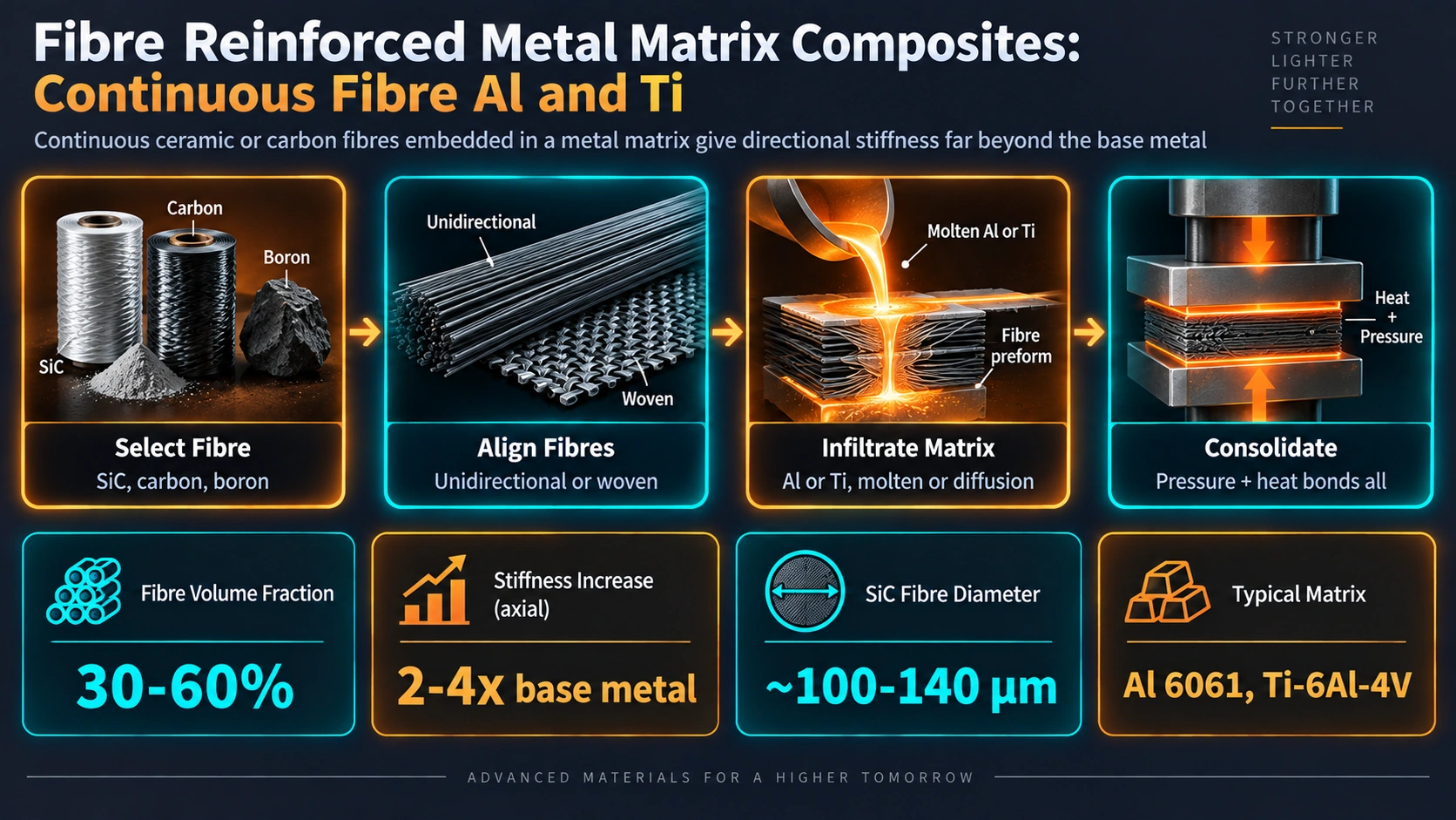
Metal matrix composites are a family of engineered materials in which a metallic alloy matrix is reinforced by one or more phases of significantly higher stiffness or strength. The reinforcement may be continuous fibres, short fibres, whiskers, or particulate. Continuous fibre MMC occupies the highest-performance tier: aligned long fibres transfer load with maximum efficiency, and the composite behaves in a strongly anisotropic manner with properties governed by the rule of mixtures in the axial direction.
Commercially significant continuous fibre systems are:
| System | Fibre | Matrix Alloy | Primary Fabrication | Key Application |
|---|---|---|---|---|
| SiC/Ti | SCS-6, SCS-Ultra, SM2156 monofilament (100μm diam) | Ti-6Al-4V, Ti-6Al-2Sn-4Zr-2Mo | Diffusion bonding (HIP or HP) | Fan blades, blisks, drive shafts, landing gear struts |
| SiC/Al | SCS-2, Nicalon (10-15μm diam); Nextel 610 (Al₂O₃) | 2xxx, 6061, 8090 Al alloys | Pressure infiltration, diffusion bonding | Space truss members, optical benches, precision mirrors |
| C/Al | Pitch-based carbon (P-100, P-120): ultra-high modulus | 6061-T6, 2024 | Liquid metal infiltration, squeeze casting | Spacecraft thermal panels, stiffness-critical booms |
| Al₂O₃/Al | Nextel 610, Saffil (δ-Al₂O₃) | LM25, A357 | Pressure infiltration of preform | Diesel piston crowns, brake drums |
Discontinuous reinforced MMC — SiC particulate/Al or Al₂O₃ particulate/Al — is excluded from this article; metal matrix composites in the Al-SiC particulate system are covered separately.
Reinforcement Fibres: Characteristics and Selection
SiC Monofilaments for Titanium Matrix Composites
The dominant reinforcement for Ti-MMC is the SiC monofilament produced by chemical vapour deposition (CVD) of methyltrichlorosilane onto a resistively heated tungsten or carbon substrate. The Textron (now Specialty Materials) SCS series and the Sigma SM series (TISICS Ltd, UK) are the two principal commercial families. Fibre diameter is approximately 100-140 μm, which is an order of magnitude coarser than small-diameter ceramic fibres.
SCS-6 vs SCS-Ultra vs SM1240/SM2156
SCS-6 fibres carry a dual-layer pyrolytic carbon surface coating (carbon-rich inner zone + SiC outer zone, total ~3 μm) that reduces interfacial reactivity. SCS-Ultra achieves tensile strength above 5.9 GPa through a more controlled deposition chemistry. SM1240 and SM2156 (TISICS) use a TiB₂ diffusion barrier in place of carbon, giving a harder interface and improved transverse strength. Key fibre properties are:
| Property | SCS-6 | SCS-Ultra | SM2156 |
|---|---|---|---|
| Diameter (μm) | 142 | 142 | 100 |
| Tensile strength (GPa) | 3.45 | 5.90 | 3.5 |
| Young's modulus (GPa) | 380-400 | 415 | 400 |
| Density (g/cm³) | 3.00 | 3.00 | 3.10 |
| CTE (10-6/°C) | 4.5 | 4.5 | 4.5 |
| Surface coating | Pyrolytic C/SiC | Pyrolytic C/SiC | TiB₂ |
Fibres for Aluminium Matrix Systems
Small-diameter (10-15 μm) SiC fibres such as Nicalon (Nippon Carbon) are used in Al-matrix continuous fibre MMC. Pitch-based carbon fibres (P-100, P-120) achieve graphitic moduli of 724-827 GPa and are the reinforcement of choice where stiffness at minimum mass is required, as in space structural applications. However, carbon reacts with aluminium above approximately 550 °C to form aluminium carbide (Al₄C₃), which is brittle and hydrolyses in humid environments, degrading strength. Titanium diboride or Si₃N₄ barrier coatings on carbon fibres extend the processing window.
Fabrication Routes for Continuous Fibre MMC
Foil-Fibre-Foil Diffusion Bonding (Ti-MMC)
The foil-fibre-foil (FFF) process is the baseline fabrication route for SiC/Ti-6Al-4V MMC panels. Alternating plies of Ti-6Al-4V foil (100-150 μm thick) and monofilament arrays wound or laid at controlled spacing are stacked to the target fibre volume fraction and ply orientation, then sealed inside a titanium or mild steel consolidation can. The can is evacuated, sealed by electron beam welding, and processed by:
- Hot isostatic pressing (HIP): 900-950 °C, 100-200 MPa Ar, 1-4 hours. Isostatic pressure ensures uniform consolidation even around fibres.
- Uniaxial hot pressing (HP): Lower cost but limited to flat panels; pressure applied through rigid platens.
Full consolidation is confirmed by density measurement and metallographic cross-section showing <1% residual porosity. The diffusion bonding mechanism involves:
- Surface oxide fracture and plastic flow at foil asperities under applied pressure
- Volume diffusion of titanium across the foil-foil interface, driven by chemical potential gradient
- Grain boundary migration consuming the original foil interfaces
- Creep densification eliminating residual voids within the microstructure
Matrix-Coated Fibre (MCF) Process
In the MCF process, titanium or titanium alloy is deposited directly onto fibre arrays by magnetron sputtering or ion beam-assisted deposition. The coated fibre tapes are then consolidated by uniaxial hot pressing at lower pressures than FFF, since the matrix is already intimately surrounding each fibre. MCF gives more uniform fibre spacing and allows net-shape consolidation into complex geometries. It is used in the manufacture of integrally bladed rotors (blisks) with MMC rings.
Liquid Metal Infiltration (Al-MMC)
For Al-matrix systems, liquid aluminium alloy at 700-750 °C is infiltrated into a fibre preform under applied gas pressure (50-150 MPa) or by squeeze casting. The preform is manufactured by winding or weaving fibres into the desired fibre architecture, then partially sintering a binder to give handling strength. Critical processing variables are:
- Wetting angle: SiC is not spontaneously wetted by aluminium (contact angle ~140°); surface coatings (Si₃N₄, Ni, Cu) or alloying with Mg reduce contact angle below 90°, enabling infiltration.
- Infiltration pressure: Must exceed the capillary threshold P = -4γ cosθ / d, where γ is surface tension and d is fibre spacing.
- Melt temperature: Higher temperature improves fluidity and wetting but accelerates interfacial reaction (Al₄C₃ formation above ~550 °C).
Fibre-Matrix Interface: Reactions and Control
The interface between fibre and matrix is the most critical microstructural feature in continuous fibre MMC. It must be strong enough to transfer load from matrix to fibre but not so strong that it prevents crack deflection — a degree of interfacial debonding is required for damage-tolerant behaviour. Interface microstructure is determined by the thermochemistry of the fibre-matrix couple during fabrication.
SiC/Ti Interfacial Reactions
Titanium is a highly reactive metal and attacks SiC even at solid-state temperatures. The reaction sequence at the SiC/Ti-6Al-4V interface during HIP at 900-950 °C is:
SiC + Ti  →  TiC + Ti₅Si₃ (dominant above 900 °C)
           →  TiSi₂ + TiC   (at lower temperatures)

Reaction layer growth follows parabolic kinetics:
  x² = k(T) · t

Arrhenius rate constant:
  k(T) = k₀ · exp(−Q / RT)

where Q ≈ 250 kJ/mol (diffusion activation energy in TiC)
      R = 8.314 J/mol·K
      T = absolute temperature (K)
      t = time at temperature (s)
A reaction layer of 1-2 μm is acceptable; beyond 2 μm, fracture toughness of the TiC/Ti₅Si₃ brittle intermetallic layer initiates fibre surface cracks under loading, reducing composite tensile strength by up to 30%. Diffusion barrier coatings (pyrolytic C in SCS-6; TiB₂ in SM2156) reduce k(T) by a factor of 5-10, extending the permissible HIP time for full consolidation.
SiC/Al Interfacial Reactions
Aluminium reacts with SiC above ~650 °C to form aluminium carbide and silicon:
4Al + 3SiC → Al₄C₃ + 3Si
Al₄C₃ is a brittle reaction product that hydrolyses in moisture-containing environments, generating aluminium hydroxide and methane, severely degrading fibre strength. The reaction is suppressed by: keeping the melt temperature below 750 °C; using Si-containing Al alloys (free Si suppresses Al₄C₃ by Le Chatelier); and applying SiO₂ or Si₃N₄ fibre coatings. Carbon fibre/Al interfaces react even faster, requiring TiB₂ or NiP barrier coatings on the fibre surface.
Mechanical Properties of Continuous Fibre MMC
Axial Properties: Rule of Mixtures
The axial Young's modulus of a continuous fibre composite is given accurately by the rule of mixtures (Voigt upper bound):
E₂ = V, · E, + (1 − V,) · Eₘ

For SiC/Ti-6Al-4V at V, = 0.35:
  E₂ = 0.35 × 390 + 0.65 × 114
       = 136.5 + 74.1
       = 210.6 GPa   (vs 114 GPa unreinforced Ti-6Al-4V)

Transverse modulus (Reuss lower bound):
  1/E⊥ = V,/E, + (1 − V,)/Eₘ
  E⊥ ≈ 144 GPa at V, = 0.35 (significantly higher than Reuss; shear lag effect)
Axial Tensile Strength and Critical Volume Fraction
Composite axial strength (simplified):
  σ , = V, · σ,* + (1 − V,) · σₘ'

where σ,* = fibre fracture strength
      σₘ' = matrix flow stress at fibre fracture strain

Critical fibre volume fraction (below which composite < monolithic matrix):
  V,(crit) = (σₘu − σₘ') / (σ,* − σₘ')

For SiC/Ti-6Al-4V: V,(crit) ≈ 0.06 (6 vol%)
→ Any fibre content above 6 vol% strengthens over unreinforced alloy
Anisotropy and Transverse Properties
The anisotropy of continuous fibre MMC is its most significant engineering limitation. At 35 vol% SiC, axial tensile strength exceeds 1800 MPa while transverse strength is only 300-400 MPa, controlled by fibre-matrix interface debond strength rather than fibre or matrix strength. This strong anisotropy requires that component loading paths be carefully aligned with fibre directions, and that multi-axial loading states be accommodated by cross-ply or helical winding architectures.
| Property | Ti-6Al-4V (monolithic) | SiC/Ti-6Al-4V 35 vol% (axial) | SiC/Ti-6Al-4V 35 vol% (transverse) |
|---|---|---|---|
| Young's modulus (GPa) | 114 | 210 | 144 |
| UTS (MPa) | 950 | 1800+ | 300-400 |
| 0.2% YS (MPa) | 880 | ~1200 (proportional limit) | 250-300 |
| Failure strain (%) | 8-10 | 0.4-0.7 | 0.3-0.5 |
| Density (g/cm³) | 4.43 | 3.90 | 3.90 |
| Specific stiffness (GPa·cm³/g) | 25.7 | 53.8 | 36.9 |
| Fatigue limit 10⁷ cycles (MPa) | ~500 | ~900 | ~180 |
Thermal Residual Stresses
On cooling from the consolidation temperature (~950 °C) to room temperature, the differential thermal contraction between SiC (α ≅ 4.5 × 10⁻⁶/°C) and Ti-6Al-4V (α ≅ 8.6 × 10⁻⁶/°C) generates a biaxial compressive residual stress in the fibre and tensile residual stress in the matrix:
Δα = αₘ − α, = 8.6 − 4.5 = 4.1 × 10⁻⁶ /°C

ΔT = −950 °C (cooling from consolidation)

Approximate matrix biaxial residual stress:
  σₘ(residual) = Eₘ · Δα · ΔT · V, / (1 − νₘ)
                ≈ +150 to +250 MPa (tensile, biaxial in matrix)

Fibre residual stress:
  σ,(residual) ≈ −300 to −500 MPa (compressive)
These thermal residual stresses are measured non-destructively by neutron diffraction or synchrotron X-ray diffraction through the composite thickness. They are superimposed on applied stresses and significantly influence fatigue crack initiation (tensile residual stress in matrix reduces fatigue life) and fibre failure (compressive pre-stress in fibre increases monotonic strength).
Elevated-Temperature Performance
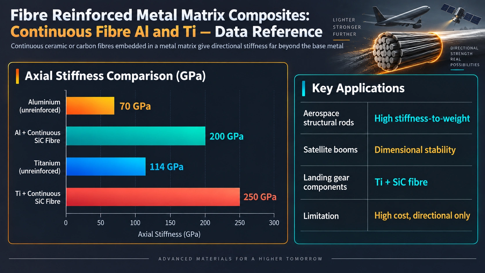
A primary driver for SiC/Ti MMC adoption in gas turbine engines is retention of stiffness and strength at temperatures where conventional Ti-6Al-4V degrades. At 500 °C, unreinforced Ti-6Al-4V loses approximately 30% of room-temperature modulus and 35% of yield strength. SiC monofilament retains >95% of room-temperature modulus at 500 °C, so the composite loses less strength per degree than the monolithic alloy. The operating temperature ceiling for SiC/Ti-6Al-4V is limited by creep of the Ti matrix and accelerated interfacial reaction, both of which intensify above 600 °C. For temperatures above 650 °C, intermetallic matrix composites (SiC/Ti₂AlNb, SiC/TiAl) extend the thermal capability, at the penalty of even lower damage tolerance.
Aerospace Applications
Ti-MMC in Aeroengine Components
The most commercially advanced application of SiC/Ti-6Al-4V MMC is the reinforced ring or annular component used in aeroengine fan and compressor stages. The Rolls-Royce Trent 1000 and GE90 engines incorporate titanium MMC components, and the Airbus A380 uses Ti-MMC in high-pressure compressor discs. In each application the geometry is deliberately chosen to exploit the anisotropic property advantage: a ring or disc loaded primarily in hoop (circumferential) tension places the high-strength, high-modulus fibre direction in the load-bearing orientation. The Ti-MMC ring replaces a heavier titanium forging, saving 25-40% component mass.
Fan blade root inserts in SiC/Ti-6Al-4V MMC enable carbon fibre composite fan blades — which cannot carry high bearing loads at the dovetail root — to be attached to the disc without titanium metal inserts, reducing blade assembly mass further. Drive shafts for helicopter gearboxes in SiC/Ti achieve specific torsional stiffness 80% higher than comparable titanium shafts.
Al-MMC in Space Structures
Carbon fibre/aluminium and SiC/aluminium continuous fibre MMC are used in space truss structures and precision optical systems where dimensional stability over wide temperature ranges is critical. The near-zero CTE achievable by tailoring Vf of pitch-based carbon fibre in Al alloy (α ≈ 1 × 10⁻⁶/°C at Vf ≅ 0.45) enables optical bench structures and mirror mounts that maintain alignment accuracy over temperature swings from −150 °C to +120 °C in low Earth orbit. The Hubble Space Telescope metering truss structure used C/Al MMC tubes for this reason.
Al₂O₃/Al for Automotive Applications
Short Saffil (δ-Al₂O₃) fibre reinforced aluminium preforms, squeeze-cast with Al-Si piston alloys, are used in diesel piston crown ring grooves (Toyota, Honda production engines since the 1980s). This is technically a short-fibre rather than continuous fibre system, included here for comparison. The reinforced piston crown reduces wear at the top ring groove from 8-10 μm/hour to <1 μm/hour, enabling longer service intervals and elimination of Ni-resist iron inserts.
Quality Assurance and Non-Destructive Evaluation
Non-destructive evaluation of Ti-MMC components is more challenging than for monolithic alloys because the high acoustic impedance contrast between SiC fibres and Ti matrix scatters ultrasound strongly. Phased array ultrasonic testing (PAUT) with high-frequency transducers (10-15 MHz) in immersion mode is the primary volumetric inspection method. Fibre misalignment, fibre clustering, inter-ply delaminations, and matrix cracks can be detected at >2 mm depth with ≈1 mm2 resolution. Computed X-ray tomography (CT scanning) provides full three-dimensional defect mapping but is expensive and limited to smaller components. Interface reaction zone thickness is verified by metallographic cross-section and SEM/EDX analysis of production witness coupons processed alongside each HIP batch.
Component qualification typically requires:
- Density measurement (>98.5% theoretical) per Archimedes method
- Flatness/warp <0.05 mm over 300 mm gauge length
- Hardness survey of matrix (typically 36-38 HRC for Ti-6Al-4V post-HIP)
- Monotonic tensile testing of companion coupons (axial and transverse)
- Fracture surface examination by SEM for fibre pull-out length and interface character
Design Considerations and Failure Modes
Continuous fibre MMC components must be designed using composite mechanics rather than isotropic design codes. Classical laminate theory (CLT) predicts ply stresses and inter-laminar shear stresses in multi-ply lay-ups. Failure criteria applicable to MMC include the maximum stress criterion, Tsai-Hill, and Tsai-Wu interactive criteria. The notch sensitivity of SiC/Ti MMC (stress concentration factor Kt reduces fatigue life by a factor of 3-5 versus unnotched specimens) requires careful geometric design to avoid stress concentrations.
Primary failure modes under service loading are:
- Longitudinal matrix cracking: initiates at fibre-matrix interface debonds at σ ≅ 0.6σUTS
- Fibre fracture: Weibull statistics govern fibre bundle failure; critical cluster size ≈ 3-5 adjacent fibre breaks
- Interface delamination: transverse tensile stress (from multiaxial loading or CTE mismatch) drives ply-by-ply delamination
- Oxidation embrittlement: at elevated temperature, oxygen ingress along matrix cracks reduces fatigue crack growth resistance
Designing around these modes requires conservative first-ply failure criteria, minimum edge distances of 3-5 fibre diameters at fastener holes, and environmental coatings for high-temperature service. For phase transformation behaviour in metallic systems and for HAZ microstructure considerations in joining MMC to monolithic alloy, refer to the dedicated articles in this series.
Frequently Asked Questions
What is the difference between continuous and discontinuous fibre MMC?
Why is SiC the dominant reinforcement fibre for metal matrix composites?
What interfacial reactions occur between SiC fibres and Ti-6Al-4V matrix?
How are SiC/Ti MMC panels manufactured by diffusion bonding?
What are the mechanical properties of SiC/Ti-6Al-4V compared to the unreinforced alloy?
What is the role of fibre volume fraction in determining MMC properties?
What fabrication routes are available for continuous fibre Al-matrix MMC?
How are thermal residual stresses managed in SiC/Ti MMC components?
What are the main failure modes in continuous fibre MMC under fatigue loading?
Recommended Reference Books
Metal Matrix Composites — Chawla & Chawla
Comprehensive treatment of MMC systems covering reinforcement types, fabrication, mechanics, and applications. Essential reference for MMC engineers.
View on AmazonTitanium: A Technical Guide — Donachie
Authoritative reference covering Ti alloy metallurgy, processing, and properties including Ti-6Al-4V matrix behaviour for MMC applications.
View on AmazonComposites Engineering Handbook — Miracle & Donaldson
ASM International volume covering design, fabrication, testing, and properties of composite materials including metal matrix systems.
View on AmazonMaterials Science and Engineering: An Introduction — Callister (10th Ed.)
Foundational materials science textbook covering composite mechanics, rule of mixtures, and interface fundamentals at undergraduate through postgraduate level.
View on AmazonDisclosure: MetallurgyZone participates in the Amazon Associates programme. If you purchase through these links, we may earn a small commission at no extra cost to you. This helps support free technical content on this site.
Further Reading
