Forging Processes: Open Die, Closed Die, Ring Rolling, and Isothermal Forging
Forging is among the oldest and most mechanically effective methods of shaping metals, yet it remains indispensable in modern aerospace, oil & gas, power generation, and automotive engineering precisely because no other bulk deformation process can so reliably eliminate porosity, align grain flow with stress trajectories, and develop the combination of strength, toughness, and fatigue life demanded by safety-critical components. This article provides a rigorous treatment of the principal forging routes — open die, closed die, ring rolling, and isothermal forging — covering deformation mechanics, metal flow, die design, microstructural evolution, defect formation, and process selection criteria.
Key Takeaways
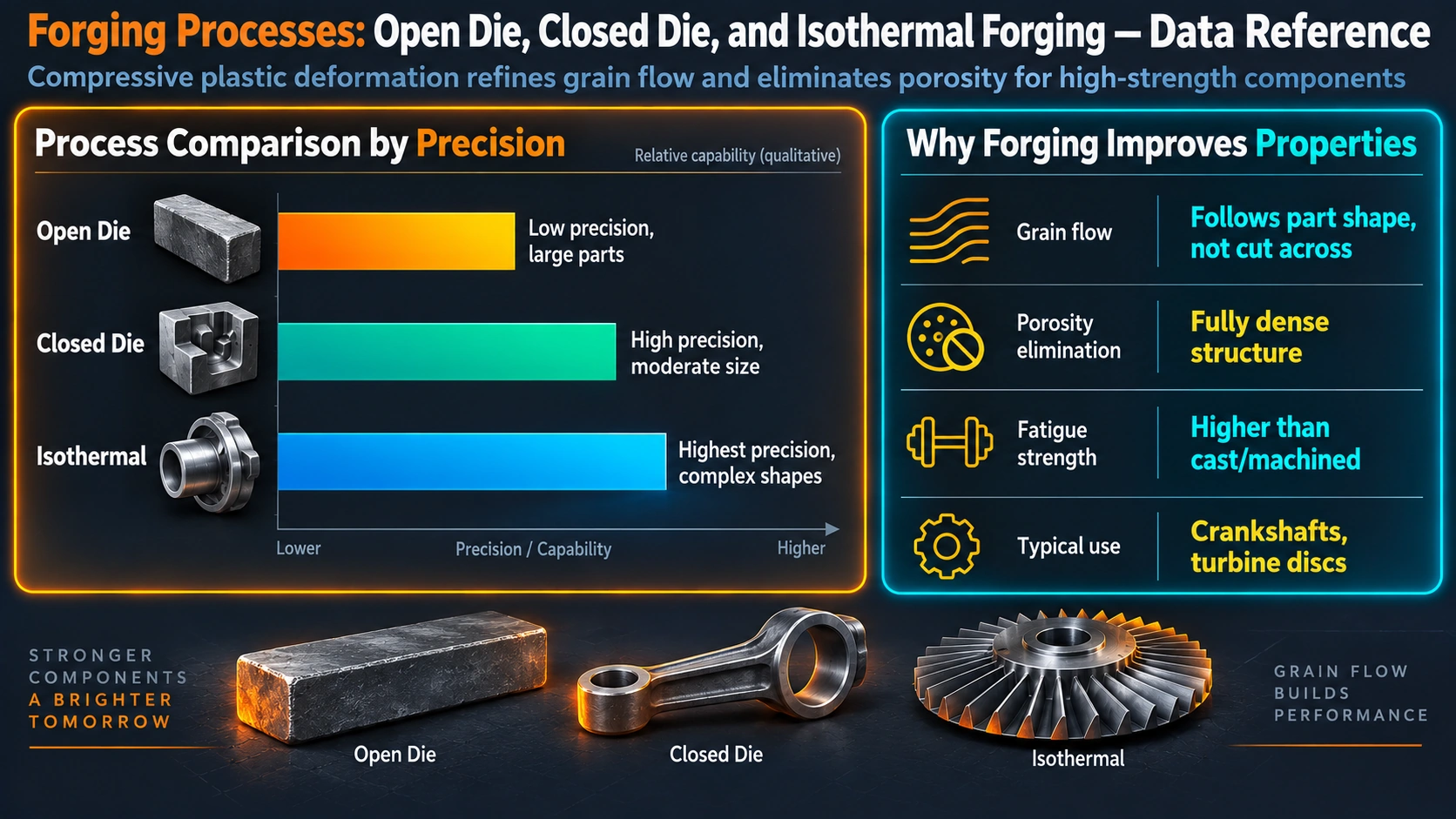
- Forging refines grain size, eliminates porosity, and develops aligned fibrous grain flow — improving strength, fatigue life, and impact toughness over equivalent cast or machined-from-bar stock.
- Open die forging suits large, simple shapes and low volumes; closed die forging produces net or near-net shapes with tight tolerances at higher volume.
- Ring rolling is an incremental forging process that generates circumferential grain flow in seamless rings up to 10 m diameter, critical for flanges, bearing races, and turbine discs.
- Isothermal forging eliminates die chilling by maintaining tool and workpiece at the same temperature, enabling near-net-shape manufacture of titanium and nickel superalloy components.
- Forging reduction ratio (R = A0/A1) must reach at least 4:1 to fully consolidate porosity; aerospace practice typically specifies 6:1 to 8:1.
- Laps, cold shuts, underfill, and internal burst are the principal defect types in closed die forgings; all are mitigated by correct preform design and finite element process simulation.
Fundamentals of Plastic Deformation in Forging
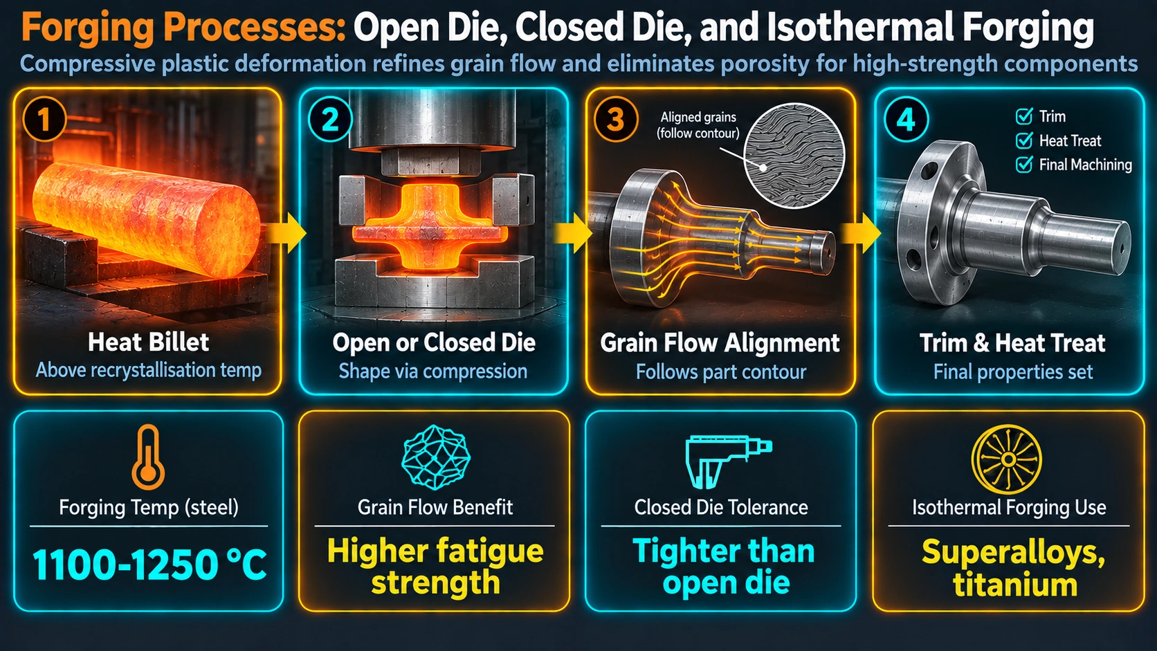
All forging processes exploit the capacity of metals above their recrystallisation temperature (hot forging) or below it (cold/warm forging) to undergo large plastic strains without fracture. The workpiece material must be driven beyond its yield stress σy uniformly throughout the deforming volume; the die geometry and lubrication system determine how that driving force is transmitted and how friction at the tool-workpiece interface influences metal flow.
Flow Stress and the Forging Pressure Equation
The mean forging pressure p required to deform a disc or slab of flow stress σf is elevated above the uniaxial flow stress by the friction hill — the build-up of hydrostatic pressure toward the centre of the contact zone as outward metal flow is resisted by friction:
Mean forging pressure (cylinder approximation):

  p_mean = σ_f × (1 + 2μR / 3h)

Where:
  σ_f  = current flow stress at temperature T and strain rate ε̇  [MPa]
  μ    = Coulomb friction coefficient at die/workpiece interface
  R    = radius of contact zone (half-width for slab)         [mm]
  h    = current height of workpiece                          [mm]

Note: The term (2μR/3h) is the friction hill factor.
As R/h increases (thin, wide workpiece), forging pressure rises steeply.
For hot forging with graphite-based lubricants, μ typically ranges from 0.1 to 0.25. With glass-lubricant systems (used in titanium and superalloy forging), μ can be as low as 0.05, significantly reducing press capacity requirements. The flow stress σf is itself a function of temperature, strain, and strain rate, described by the Zener-Hollomon parameter:
Zener-Hollomon parameter:

  Z = ε̇ × exp(Q_def / RT)

Where:
  ε̇    = strain rate                        [s⁻¹]
  Q_def = activation energy for deformation  [J/mol]  ≈ 300 kJ/mol for austenite
  R     = gas constant = 8.314              [J/mol·K]
  T     = absolute temperature               [K]

High Z (high strain rate, low temperature) → high σ_f → higher forging loads
Dynamic and Metadynamic Recrystallisation
During hot forging of steels and nickel alloys above the no-recrystallisation temperature (Tnr), accumulated dislocation density triggers dynamic recrystallisation (DRX) when the strain exceeds the critical strain εc (typically 0.5–0.8 of the peak strain εp). DRX nucleates new strain-free grains at prior grain boundaries, subgrain boundaries, and deformation bands, progressively replacing the deformed structure. After each forging pass, metadynamic recrystallisation (MDRX) continues in the inter-pass interval using stored energy from the prior deformation, further refining the austenite grain before subsequent passes or quench.
Open Die Forging
Open die forging (also called smith forging or flat die forging) uses two flat or simply contoured dies between which the workpiece is repeatedly deformed and repositioned. It is the most flexible of the major forging routes — capable of producing ingots up to 500 tonnes and shaft lengths exceeding 20 m — but yields the lowest dimensional accuracy, requiring substantial machining allowance.
Process Mechanics
The primary operations in open die forging are upsetting (reducing height to increase diameter), drawing out (reducing cross-section to increase length), and cogging (sequential upsetting strokes along the length of a large ingot to reduce its cross-section). During cogging, each press blow deforms a localised zone; the adjacent undeformed material acts as a rigid constraint, generating lateral compressive stresses that aid consolidation of centreline porosity.
Forging Reduction Ratio
Forging reduction ratio (work ratio):

  R = A₀ / A₁

Where:
  A₀ = original cross-sectional area  [mm²]
  A₁ = final cross-sectional area     [mm²]

Minimum R for acceptable consolidation of central porosity: 4:1
Aerospace shaft and disc practice: 6:1 to 8:1
Required R for vacuum arc remelted (VAR) or electroslag remelted (ESR) ingots
used in turbine discs: often specified at ≥ 4:1 from ingot to billet,
then ≥ 3:1 from billet to disc pre-form.
Ingot Conversion — Cogging
Large steel ingots are produced by casting into bottom-poured moulds. Solidification creates a macrosegregated structure with centreline porosity, pipe, and A- and V-segregates. Cogging on a hydraulic open die press with bite ratios (reduction per pass / original height) of 15–30% progressively heals this porosity by closing voids under triaxial compressive stress and welding them shut by diffusion bonding. The number of cogging heats, bite sequence, and rotation protocol are managed by press operators following heat-specific process sheets. For very large ingots (> 50 t), multiple reheat cycles between press stages are required to restore forging temperature.
Applications of Open Die Forging
Open die forging produces: large shafts for ship propulsion, generators, and wind turbines; pressure vessel shells and flanges; rolls for rolling mills; marine crankshafts; tool steel blocks; and bespoke large structural components where tooling cost for closed die forging cannot be justified at the production volume. The annealing and normalising heat treatment applied after cogging refines the coarse-grained structure and relieves forging stresses before further processing.
Closed Die Forging
Closed die forging (impression die forging) uses matched upper and lower dies with machined cavities that constrain metal flow to produce a shape approximating the finished component with controlled flash at the parting line. It delivers tight dimensional tolerances (typically ±0.5–2.0 mm on critical dimensions depending on material and size), excellent surface finish, and consistent grain flow with high production rates, justifying the substantial die investment for medium to high production volumes.
Die Design and Flash Geometry
The flash land and gutter geometry are critical to closed die forging quality. The flash land (the narrow restriction between the die cavities and the flash gutter) creates a back-pressure that forces metal to fill the die cavity completely before escaping. Flash land thickness (tf) is typically selected at 3–5% of the plan area equivalent diameter, with a land width (wf) of 3–6tf. Too narrow a flash land produces premature flash and underfilling; too wide creates excessive forging loads and thermal fatigue damage to the die corner.
| Die Zone | Function | Design Parameter | Consequence of Error |
|---|---|---|---|
| Impression cavity | Defines forged shape | Draft angles 3–7° | Insufficient draft → die lock / ejection failure |
| Flash land | Back-pressure to fill cavity | tf = 3–5% of equivalent diameter | Too thin → underfill; too thick → excessive load |
| Flash gutter | Flash accommodation | Volume ≥ 1.5× expected flash volume | Flash overfill → die damage / flash fold-back |
| Ejector pins / knockout | Part extraction | Positioned at neutral metal flow zones | Incorrect placement → forging damage on ejection |
| Die corner radius | Metal flow into ribs / bosses | rd ≥ 3–5 mm (hot), 1–2 mm (cold) | Sharp corner → lap defects; excessive fillet → shape inaccuracy |
Preform (Blocker) Design
Optimum metal flow in the finish die impression requires that the billet volume be redistributed into a preform shape — the blocker — before the finish die impression. The blocker achieves three goals: distributes volume to avoid localised underfill or overfill in the finish impression; establishes the grain flow direction in the finished forging; and controls where the flash forms at the parting line. FE simulation using software such as Deform, Forge NxT, or Simufact Forming has substantially replaced empirical trial-and-error blocker design, allowing engineers to predict fold formation, identify temperature gradients that risk cold shut defects, and optimise strain distribution before committing to die manufacture.
Grain Flow and Its Mechanical Significance
The fibrous grain flow developed during closed die forging — visible in macro-etched sections as a streamline pattern of prior austenite boundaries, non-metallic inclusions, and secondary phases — confers markedly anisotropic properties. Strength and ductility in the longitudinal direction (along flow) exceed transverse properties by 10–25% in steels with significant inclusion content. Correct preform design ensures that this fibre follows the external contours of the forging — particularly at highly stressed regions such as fillet radii in crankshafts and at the web-rib junction in connecting rods — mirroring the design intent for a quench and tempered structural component.
Equipment for Closed Die Forging
Closed die forging equipment falls into three main categories: gravity drop hammers (board or air-lift), powered counterblow hammers, and mechanical or hydraulic presses. Each differs in energy-stroke characteristics and their interaction with die fill and flash formation:
| Equipment Type | Stroke Characteristic | Strain Rate [s-1] | Advantages | Limitations |
|---|---|---|---|---|
| Gravity drop hammer | Energy limited | 50–500 | Low capital cost, flexible | Vibration, noise, energy inefficiency |
| Counterblow hammer | Energy limited | 50–300 | Balanced forces, minimal foundation requirement | Complex tooling setup |
| Mechanical press (eccentric/knuckle) | Stroke limited | 10–30 | Consistent stroke length, auto-transfer integration | Fixed stroke; die height adjustment required |
| Hydraulic press | Load limited | 0.01–10 | Full load available throughout stroke; slow for isothermal | High capital cost; slower than mechanical |
| Screw press | Energy limited | 20–100 | Good for precision forgings; controllable blow energy | Lower productivity vs. mechanical press |
Ring Rolling
Ring rolling is a rotary forging process that converts a preform ring (produced by piercing and cropping) into a seamless ring of controlled cross-section by progressive reduction between a driven main roll and an idle mandrel roll. Axial conical rolls (edger rolls) simultaneously control ring height. The process generates circumferential grain flow — aligned tangentially around the ring — which confers superior fatigue crack propagation resistance in the critical hoop direction for pressure vessel flanges, bearing races, and rotating turbine discs.
Ring Rolling Process Sequence
The full manufacturing route for a ring-rolled component involves: (1) billet saw or shear cropping; (2) open die upsetting to the required billet height; (3) piercing on a vertical press to create the preform ring; (4) ring rolling to near-net shape; (5) straightening / roundness correction; (6) heat treatment; and (7) rough machining and non-destructive examination. Flash is absent from ring rolling — all billet volume is retained in the ring, so volume management (billet mass calculation) is critical.
Roll Pass Design and Ring Growth Rate
The instantaneous ring growth rate during rolling must be controlled to maintain ring roundness and avoid oval or polygonal distortion. Radial feed rate of the main roll (vr) and the ring outer diameter D at any instant are related to the axial elongation strain rate by continuity:
Ring growth rate (simplified):

  dD/dt = (2 × v_r × D) / (D_o − D_i)

Where:
  D_o  = outer diameter of ring at current pass   [mm]
  D_i  = inner diameter of ring at current pass   [mm]
  v_r  = radial feed rate of main roll            [mm/s]

Ring growth rate typically maintained: 3–15 mm/s
Excessive growth rate → oval distortion → guide rolls required
Guide rolls positioned at 90° to the main roll contact support the growing ring and correct roundness. Sophisticated ring mills incorporate closed-loop CNC control of main roll feed rate, using diameter measurement by laser or encoder to maintain roundness within specified tolerances during growth.
Products and Industry Standards
Ring rolled products include: ASME B16.5 / B16.47 flanges for pressure piping; API 6A wellhead body forgings; inner and outer rings for large rolling element bearings (ABMA standards); jet engine compressor disc forgings (AMS 2371, AMS 4928 for titanium); wind turbine slew bearing rings (DIN 17230 for bearing steels); and heavy ring forgings for nuclear reactor pressure vessels per ASME Section III. Maximum ring diameter from the world’s largest ring mills (Wagner, SMS, Rotek) exceeds 9 m for wind turbine and mining applications.
Isothermal Forging
Isothermal forging eliminates the die-chilling effect that constrains conventional hot forging of low-thermal-conductivity, narrow-forging-window alloys. By maintaining the die at the same temperature as the workpiece (typically 900–1000°C for titanium alloys and 980–1120°C for nickel superalloys), the process achieves uniform, low flow stresses throughout the deformation zone, enabling near-net-shape forming of complex aerodynamic geometries with minimal machining allowance — critical for buy-to-fly ratio reduction in aerospace manufacturing.
Materials Processed by Isothermal Forging
The principal materials requiring isothermal or hot-die forging (a semi-isothermal variant where die temperature is elevated but not fully matched) include:
| Material Class | Representative Alloys | Forging Temperature [°C] | Die Material | Atmosphere |
|---|---|---|---|---|
| Nickel superalloys | IN718, IN100, Waspaloy, René 95 | 980–1120 | TZM molybdenum alloy | Vacuum |
| Titanium alloys | Ti-6Al-4V, Ti-6Al-2Sn-4Zr-6Mo | 900–1000 (α+β) | Ni superalloy (IN100) | Vacuum or inert gas |
| Titanium aluminides | Ti-48Al-2Cr-2Nb | 1150–1250 | TZM or Mo alloy | Vacuum |
| Aluminium alloys | 2024, 7075, 7050 | 380–460 | H13 hot work die steel | Air (lubricant-protected) |
Superplastic Isothermal Forging
Certain alloys processed under isothermal conditions at very low strain rates (10-4–10-2 s-1) in a fine-grained condition exhibit superplasticity — elongations exceeding 500% without necking. This regime allows near-complete die fill at forging pressures 50–80% below those required for conventional hot forging, enabling very complex thin-web integrally bladed ring (IBR) disc geometries to be produced in a single isothermal press stroke. The microstructural stability required for superplastic flow demands a grain size below 10 μm maintained stable at the forming temperature — achieved in IN100 and René 95 by controlled thermomechanical pre-processing and powder metallurgy route starting material.
Warm Forging and Cold Forging
Not all forging is conducted at elevated temperature. Warm forging (0.3–0.6 Tm) and cold forging (below 0.3 Tm) are used where dimensional precision, surface finish, and work hardening are advantageous and where the higher forging loads are within equipment capacity.
Cold Forging
Cold forging (room temperature, typically for carbon and low-alloy steels below 0.35% C, and for aluminium, copper, and stainless steel alloys) produces components to very tight tolerances (IT7–IT9 for steels), excellent surface finish (Ra 0.4–1.6 μm), and with significant work hardening that increases yield strength 30–80% above the annealed value. Principal operations include cold heading (bolt, screw, and fastener production), cold extrusion, and cold coining. The hardness increase from cold work follows approximately:
Flow stress of cold-worked material (power law hardening):

  σ = C × ε^n

Where:
  σ  = true stress at true strain ε   [MPa]
  C  = strength coefficient           [MPa]   (Steel 0.1%C: C ≈ 540 MPa)
  n  = strain hardening exponent               (Steel 0.1%C: n ≈ 0.26)
  ε  = true (logarithmic) plastic strain

True strain in cold forging:
  ε = ln(A₀/A₁) = ln(h₀/h₁) for upsetting
Warm Forging
Warm forging of steels at 650–950°C offers a compromise: lower flow stresses and reduced work hardening compared to cold forging, combined with better dimensional accuracy and oxidation control compared to conventional hot forging. It is widely used for bevel gears, universal joint crosses, and precision automotive components where net-shape or near-net-shape forging reduces or eliminates subsequent machining. Scale formation is minimal in the warm range when induction heating is used for short soak times before pressing.
Forging Defects — Classification and Prevention
Surface Defects
Laps are seam-like surface discontinuities created when a metal fold is pressed against a die face, trapping an oxide film at the interface that prevents metallurgical bonding. They arise from excess billet volume squeezing back over die corners, sharp die radii, or abrupt changes in forging direction. Scale pits form when oxide scale is pressed into the forging surface during die contact without being fully descaled beforehand. Both are detectable by magnetic particle inspection or fluorescent penetrant testing.
Internal Defects
Internal bursts (central burst or chevron cracking) occur during drawing-out or extrusion when tensile stresses on the axis of a workpiece exceed the local ductility — typically in free-machining steels with high sulphur content, or materials with low ductility at the forging temperature. They are detected by ultrasonic testing per ASTM A388. Hydrogen flakes are a separate internal defect in large alloy steel forgings caused by hydrogen supersaturation during cooling; they appear as bright, smooth internal cracks on fracture surfaces. Prevention requires slow controlled cooling after forging and optionally hydrogen degassing (vacuum treatment or prolonged subcritical annealing at 200–300°C).
Dimensional and Microstructural Defects
Underfill results from insufficient billet volume, excessively low forging temperature (high flow stress prevents complete die fill), or inadequate flash land back-pressure. Grain coarsening occurs when forging temperature exceeds the grain-growth temperature of the alloy and the subsequent cooling rate does not suppress grain growth by transformation or precipitation pinning. In nickel superalloys, coarse grains in the δ-solvus-exceeded zone cause a step change in low-cycle fatigue life and are cause for rejection per AMS 2175. Banding in steel forgings — alternating ferrite-rich and pearlite-rich layers aligned with the working direction — originates from compositional segregation in the original ingot and is mitigated by increased forging reduction ratio and high-temperature homogenisation heat treatment.
Post-Forging Heat Treatment and Microstructure
Forging establishes the shape and grain flow, but the mechanical property profile is finalised by post-forging heat treatment. For carbon and low-alloy steels, the standard sequence is normalise (after forging, before machining) followed by quench and temper (after rough machining, before final inspection). Normalising relieves forging stresses and refines the coarse-as-forged austenite grain structure, while quenching and tempering develops the final combination of strength and toughness. The martensite formed on quenching from the austenitising temperature is tempered to the required hardness and impact transition temperature to meet the design specification.
For titanium forgings processed in the (α+β) field, a solution treat and ageing (STA) sequence transforms the worked microstructure into a bi-modal structure (primary equiaxed α in a transformed-β matrix) optimised for tensile and fatigue performance. Nickel superalloy turbine disc forgings receive a complex multi-step supersolvus or subsolvus solution treatment, quench, and multi-stage ageing sequence calibrated to produce the correct combination of γ’ precipitate size distribution for creep and fatigue resistance at operating temperature.
Industrial Applications and Standards
Aerospace and Gas Turbine
Gas turbine compressor and turbine disc forgings in nickel superalloys and titanium are among the most demanding forgings manufactured. They must meet AMS 2375 (nickel alloy forgings), AMS 4928 (Ti-6Al-4V bar and billet), and the prime contractor’s proprietary material specifications. Ultrasonic inspection to AMS 2154 Class AA or equivalent is mandatory for all rotating turbine hardware. Grain size must be certified to ASTM E112 requirements, and macroetch inspection (ASTM E340) verifies grain flow and freedom from seams and laps at every lot.
Oil and Gas / Pressure Equipment
Flanges, valves, and pressure-containing components for oil and gas service are forged to ASTM A182 (alloy steel), ASTM A522 (9% Ni cryogenic), or ASTM A336 (Class grades for pressure vessels) and inspected per ASME Section VIII Div. 1 or API 6A. Sour service forgings must additionally meet NACE MR0175/ISO 15156 hardness limitations (HRC 22 max for carbon and low-alloy steels) to prevent sulphide stress cracking. The corrosion resistance of the finished forging is often verified by NACE TM0177 SSC testing.
Automotive and Heavy Transport
High-volume automotive forgings — crankshafts, connecting rods, steering knuckles, wheel hubs, and constant velocity joint components — are produced on mechanical presses and hammers at rates of 60–300 pieces per hour. Microalloyed forging steels (HSLA grades such as 30MnVS6, 38MnVS6 per EN 10267) allow direct cooling after forging to produce the final tempered martensite or bainite-ferrite microstructure without a separate quench and temper operation, substantially reducing energy cost and process cycle time. The grain boundary pinning by VN and MnS precipitates controls grain size during the direct cooling cycle.
Process Selection — Comparative Summary
| Criterion | Open Die | Closed Die | Ring Rolling | Isothermal |
|---|---|---|---|---|
| Dimensional tolerance | ±3–10 mm | ±0.5–2.0 mm | ±1.0–3.0 mm | ±0.3–1.0 mm |
| Shape complexity | Simple (discs, shafts) | High (3D contoured) | Axisymmetric ring | Very high (near-net) |
| Material range | All forgeable alloys | All forgeable alloys | All forgeable alloys | Difficult alloys (Ti, Ni) |
| Production volume | 1–100 pieces | 100–500,000+ | 50–50,000 | 10–5,000 |
| Tooling cost | Low | High (dies: $10k–$500k) | Medium | Very high (Mo/Ni dies) |
| Buy-to-fly ratio | 5:1–20:1 | 2:1–5:1 | 1.5:1–3:1 | 1.05:1–1.5:1 |
| Key advantage | Flexibility, large parts | Consistency, grain flow | Circumferential grain flow | Near-net shape, difficult alloys |
| Representative products | Generator shafts, rolls | Crankshafts, discs, flanges | Bearing rings, turbine discs | Ti & Ni disc forgings |
Frequently Asked Questions
What is the difference between open die and closed die forging?
Why does forging improve mechanical properties compared to casting?
What is isothermal forging and when is it used?
What is the forging reduction ratio and why does it matter?
What causes laps and cold shuts in closed die forgings?
How is grain flow controlled in a closed die forging?
What is ring rolling and what products does it make?
What die materials are used in hot closed die forging and what limits their life?
How does forging temperature affect the microstructure of steel forgings?
What non-destructive testing methods are applied to forgings?
Recommended References
ASM Handbook Vol. 14A: Metalworking — Bulk Forming
The definitive reference covering forging, rolling, extrusion, and drawing processes with process mechanics, die design, and materials data.
View on AmazonForging Handbook — Altan, Oh & Gegel
Classic text on forging process mechanics, equipment selection, die design, lubrication, and process simulation — essential for practising forging engineers.
View on AmazonMetal Forming and the Finite Element Method — Kobayashi, Oh & Altan
Rigorous treatment of FE simulation applied to metal forming including forging, with worked examples for die design and defect prediction.
View on AmazonSuperalloys: A Technical Guide — Donachie & Donachie
Comprehensive guide to nickel, cobalt, and iron-base superalloys covering isothermal and hot-die forging, heat treatment, and aerospace applications.
View on AmazonFurther Reading
Iron-Carbon Phase Diagram
Complete guide to Fe-C equilibrium, phase regions, and microstructure prediction.
Martensite Formation in Steel
Mechanism, crystallography, and mechanical consequences of martensitic transformation.
Quenching and Tempering
Process parameters, microstructural evolution, and property development in Q&T steels.
Annealing and Normalising
Heat treatment cycles for stress relief, grain refinement, and homogenisation after forging.
Grain Boundaries — Types, Energy, Segregation
Structure and properties of grain boundaries critical to hot workability and fracture behaviour.
Charpy Impact Testing
Test methodology, transition temperature determination, and acceptance criteria for forgings.
Hardness Testing Methods
Brinell, Rockwell, and Vickers hardness measurement as applied to forging QC and specification compliance.
Corrosion Mechanisms
Electrochemical and mechanistic basis of corrosion in forged components in aggressive service environments.
