Continuous Casting of Steel: Solidification, Defects, and Process Control
Continuous casting (CC) is the dominant route by which liquid steel from the basic oxygen furnace or electric arc furnace is converted into solid semi-finished sections — slabs, blooms, and billets — for subsequent rolling and forming. Globally, over 96% of steel produced is now continuously cast, displacing the older ingot-casting route entirely for most product categories. Understanding the solidification physics, heat transfer, tundish metallurgy, and defect formation mechanisms that govern CC quality is essential for process metallurgists, quality engineers, and anyone involved in steel specification and downstream processing.
Key Takeaways
- Continuous casting achieves >95% metallic yield and eliminates primary rolling stages, giving it a decisive cost advantage over ingot casting.
- The mould heat flux profile (peak 1.5–2.5 MW/m² at the meniscus) controls initial shell formation; non-uniform extraction drives surface crack defects.
- Secondary cooling by water spray governs the metallurgical length of the liquid crater; the strand must be fully solid before the straightening zone.
- Centreline segregation arises from solute enrichment of the final solidifying liquid and is controlled by soft reduction and electromagnetic stirring (EMS).
- Mould powder (flux) performs four simultaneous functions: lubrication, thermal insulation, inclusion absorption, and oxidation prevention.
- The peritectic reaction in the 0.09–0.17% C range causes volume contraction at the meniscus, making these grades most susceptible to surface longitudinal cracks.
The Continuous Casting Process: Overview
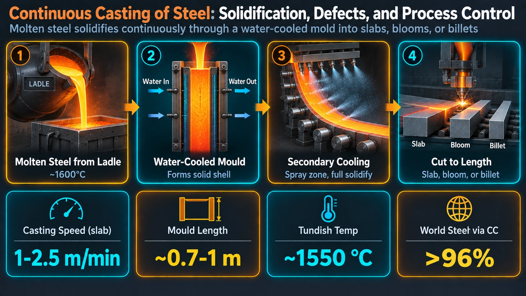
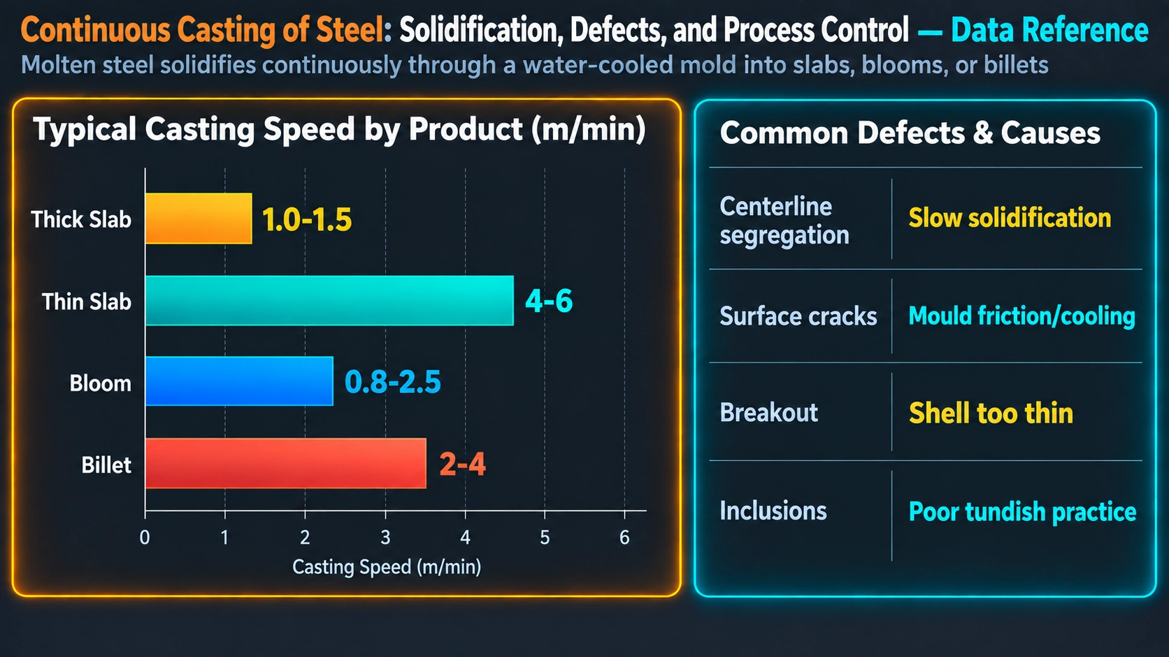
In continuous casting, liquid steel is poured from the ladle into the tundish via a refractory-lined ladle shroud. From the tundish, steel flows through a submerged entry nozzle (SEN) into the mould, which is a water-cooled copper tube oscillating vertically at 80–300 cycles per minute. The outer layer of liquid steel freezes against the mould wall, forming a solid shell typically 10–20 mm thick by the mould exit. This shell, still containing a large liquid core (the “liquidus crater”), is withdrawn downward by driven rolls at a casting speed of 0.8–2.5 m/min for slabs or up to 5–6 m/min for small billets. Water sprays in the secondary cooling zone progressively solidify the strand until the crater tip is reached. The strand is then straightened from curved to horizontal by a series of pinch rolls, cut to length by a flame cutter or mechanical shear, and discharged to the hot charge or slab yard.
Machine Configurations
Most modern CC machines are curved or bow-type: the strand follows a circular arc from the vertical mould exit to the horizontal discharge line. The radius of curvature is typically 5–12 m for slab casters and 4–8 m for bloom/billet machines. Vertical-curve and vertical machines eliminate the upper curved-strand zone, improving inclusion flotation but at greater machine height. Thin-slab casting, developed in the 1980s (Nucor/ISP technology), uses a funnel-shaped mould to cast slabs 40–90 mm thick directly, coupling casting and hot rolling in a single continuous operation.
| Section Type | Dimensions (typical) | Casting Speed | Primary Application |
|---|---|---|---|
| Slab (conventional) | 150–300 mm thick, 600–2600 mm wide | 0.8–2.0 m/min | Flat products (sheet, plate, strip) |
| Thin slab | 40–90 mm thick, 900–1680 mm wide | 4–6 m/min | Hot-rolled coil (mini-mill route) |
| Bloom | 200×200 mm to 400×600 mm | 0.5–1.5 m/min | Sections, rails, heavy bar |
| Billet | 100×100 mm to 180×180 mm | 2.0–6.0 m/min | Wire rod, rebar, seamless tube |
| Round bloom | Ø200 mm to Ø800 mm | 0.3–0.8 m/min | Seamless pipe, forged rings |
Tundish Metallurgy
The tundish performs a dual role in modern steelmaking: it acts as a surge vessel ensuring a continuous supply of liquid steel to the mould, and as a secondary metallurgical reactor for cleanliness and temperature control. Tundish capacity ranges from 15 tonnes on billet machines to over 80 tonnes on large slab casters. Residence times of 8–15 minutes allow Stokes’ law flotation of inclusion particles with diameter >50 μm, though smaller inclusions (<20 μm) are largely unaffected by gravity and require turbulence suppression for removal.
Flow Control Devices
Tundish flow must be optimised to maximise inclusion flotation while minimising short-circuiting (plug flow bypassing the bulk volume). The main internal flow control devices are:
- Dams and weirs: Submerged dams force steel upward, increasing residence time; weirs deflect the steel surface flow and prevent slag carry-over from the ladle impact zone.
- Turbostop: A refractory baffle placed directly below the ladle shroud impact point to dissipate turbulent kinetic energy, reducing argon bubble entrainment and inclusion re-suspension.
- Inhibitors (retaining walls with holes): Perforated retaining walls redirect flow and homogenise the temperature profile across a multi-strand tundish (typical for billet casters serving 4–8 strands simultaneously).
Tundish Powder and Cover
A covering flux (tundish powder) is applied over the steel surface in the tundish to provide thermal insulation, prevent steel reoxidation by atmospheric oxygen, and absorb floating inclusion particles. Tundish powders are typically based on rice husk ash, SiO2-CaO-Al2O3 formulations with low iron oxide content. Induction heating of the tundish shell is used in some installations to maintain superheat within tight limits (±5°C) over the full casting sequence.
Mould Heat Transfer and Shell Formation
The copper mould performs the most critical heat-transfer function in the CC process: extracting sufficient heat to form a shell strong enough to contain the ferrostatic pressure of the liquid pool as the strand exits the mould bottom. Copper is chosen for its high thermal conductivity (380–400 W/m·K), though working surfaces are typically nickel- or chromium-plated to improve wear resistance and reduce thermal conductivity slightly, thereby moderating the peak heat flux at the meniscus.
Heat Flux Profile
Heat flux through the mould wall is strongly non-uniform with distance from the meniscus. In the upper mould (first 50–100 mm), heat flux peaks at 1.5–2.5 MW/m² as liquid steel first contacts the mould wall and an initial solid shell forms rapidly. As the shell thickens and contracts away from the mould wall under the combined effects of thermal shrinkage and ferrostatic pressure, an interfacial air/flux gap develops, reducing heat transfer to 0.5–1.0 MW/m² by the mould exit. Mould flux infiltrating the gap partially restores heat transfer in a controlled manner depending on flux viscosity and crystallisation behaviour.
d = K × t^(1/2)
where:
  d = shell thickness (mm)
  t = time below meniscus (s)
  K = solidification constant, typically 25–30 mm/min^(1/2) for slab casting

Mould exit shell thickness (for mould length L = 900 mm, speed v = 1.2 m/min):
  t_mould = L / v = 0.90 / (1.2/60) = 45 s
  d_exit = 27 × 45^(1/2) = 27 × 6.7 = ~181 mm [Note: formula gives cm-scale result for medium K]
  Typical actual d_exit: 15–25 mm for slab, 8–15 mm for billet
Mould Oscillation and Negative Strip
The mould oscillates sinusoidally (or with a modified waveform) at a frequency f of 80–300 cpm and stroke amplitude A of 3–12 mm. Oscillation prevents the solidifying shell from sticking to the mould wall (which would cause a breakout, the catastrophic rupture of the shell and spilling of liquid steel). The critical parameter is the negative-strip ratio (NSR), defined as the fraction of each oscillation cycle during which the mould descends faster than the strand withdrawal speed, allowing the mould to stroke ahead of the shell and provide a lubricating squeeze. NSR of 15–35% is typical.
Oscillation mark pitch, p = v_c / f
  where v_c = casting speed (m/min), f = frequency (min^-1)

Example: v_c = 1.2 m/min, f = 150 cpm
  p = 1200 mm/min / 150 min^-1 = 8.0 mm/oscillation mark

Negative strip ratio (sinusoidal):
  NSR = (1/π) × arccos(v_c / (2πf×A)) × 100%
  Controls: hook depth, transverse crack susceptibility
Secondary Cooling: Spray Zone Metallurgy
Beyond the mould exit, the partially solidified strand passes through the secondary cooling zone, which extends from the mould exit to the point at which the liquid core is fully solidified (the metallurgical length, Lm). This zone typically spans 10–25 m for slab casters. Cooling is applied by arrays of water spray nozzles (and/or air-water mist nozzles in the later zones) arranged in segments supported by driven containment rolls.
Metallurgical Length and Crater End
The metallurgical length Lm defines the distance from the meniscus to the crater tip, where the last liquid steel solidifies. It is a critical design and control parameter:
L_m = (v_c × D^2) / (4K^2)
where:
  v_c = casting speed (m/s)
  D   = section thickness (m)
  K   = solidification constant (m^(1/2)·s^(-1/2)) [~0.30–0.35 typical]

Example: v_c = 0.020 m/s (1.2 m/min), D = 0.230 m slab
  L_m = (0.020 × 0.053) / (4 × 0.096) = 0.00106 / 0.384 ≈ 18.4 m
If the straightening point of a curved machine is at, say, 16 m, and the metallurgical length is 18 m, the strand will be straightened while still containing a liquid core — causing internal crack formation at the solidification front as tensile strains from unbending exceed the ductility of the hot, partially solidified steel. This risk drives the design rule: casting speed must be controlled so that Lm is always less than the machine metallurgical length.
Secondary Cooling Zones
Secondary cooling is subdivided into segments, each with independently controlled water flow. A typical slab caster has five to eight cooling segments. The total specific water flow (litres per kilogram of steel cast) ranges from 0.6 to 2.5 L/kg depending on steel grade and speed. Low-carbon steels require more aggressive cooling to prevent the high-temperature ductility trough near 900°C that promotes transverse cracking during unbending.
Solidification Microstructure
The microstructure that develops during CC solidification is governed by the constitutional supercooling and thermal gradient at the solid-liquid interface. Three distinct zones are typically observed in cross-section (Fig. 2):
Chill Zone
At the strand surface, rapid heat extraction from the copper mould produces a very high thermal gradient and a large number of nucleation sites on the mould wall surface. This results in a thin (1–3 mm) layer of fine, randomly oriented equiaxed grains — the chill zone. These grains solidify rapidly and form the first load-bearing shell.
Columnar Zone
As the solid-liquid interface advances inward, grains with their preferential crystal growth direction (⟨100⟩ for cubic iron) aligned with the heat flux direction grow competitively at the expense of unfavourably oriented grains, producing a columnar structure of long, parallel primary dendrites oriented perpendicular to the strand surface. Columnar dendrites in steel have primary arm spacings (λ1) of 300–1000 μm and secondary arm spacings (λ2) of 50–300 μm depending on local solidification rate.
λ_2 = a × (dT/dt)^(-n)
where:
  dT/dt = local cooling rate (K/s)
  a, n  = alloy-dependent constants
  For plain carbon steel: a ≈ 148, n ≈ 0.38 (giving λ_2 in μm for dT/dt in K/s)

Lower cooling rate → coarser SDAS → wider interdendritic channels → more severe microsegregation
Central Equiaxed Zone and the Columnar-to-Equiaxed Transition (CET)
In many strand cross-sections, columnar growth is arrested at some point and replaced by randomly oriented equiaxed grains in the centre — the columnar-to-equiaxed transition (CET). The CET occurs when the constitutional supercooling ahead of the columnar front is large enough to nucleate free equiaxed grains (from either dendrite fragments or heterogeneous nuclei) before the advancing columnar interface can engulf them. A large equiaxed zone is generally desirable as it reduces the severity of centreline segregation. Mould EMS, reduced superheat, and the addition of inoculant particles (e.g., TiN in titanium-bearing grades) all promote a larger equiaxed fraction.
Segregation in Continuous Cast Products
Segregation — the non-uniform distribution of solute elements — is an inherent consequence of the solidification process in multi-component alloy systems. It occurs at two scales in CC products: microsegregation between dendrite arms, and macrosegregation at the strand scale.
Microsegregation
During dendritic solidification, solute elements with equilibrium partition coefficient k < 1 (carbon, sulphur, phosphorus, manganese) are rejected into the interdendritic liquid, enriching it progressively. This results in concentration gradients across individual dendrite arm spacings (50–300 μm scale). The classic Scheil equation describes the limiting case (no back-diffusion in solid):
C_s = k × C_0 × (1 - f_s)^(k-1)
where:
  C_s  = solid composition at fraction solidified f_s
  C_0  = initial melt composition
  k    = equilibrium partition coefficient (k < 1 for segregating elements)

For sulphur in steel: k ≈ 0.035 → severe interdendritic enrichment
For carbon in steel: k ≈ 0.20–0.35 → moderate enrichment at centreline
Centreline Segregation and Macrosegregation
At the strand scale, the most industrially significant macrosegregation is centreline segregation — enrichment of C, Mn, S, and P at the geometric centre of the strand. It arises because the interdendritic liquid in the mushy zone, progressively enriched by solute rejection, flows toward the centreline under the combined driving forces of solidification shrinkage (0.3–0.5 vol% for carbon steel) and thermal contraction. The V-segregation pattern seen in Baumann prints or acid-etched cross-sections is produced by intermittent flow of enriched liquid along the steep temperature gradient near the crater end.
Centreline segregation is quantified by the Segregation Index (SI) or the ratio Ccentre/Cbulk. For continuously cast slab, SI values of 1.05–1.15 for carbon are typical; values >1.20 indicate poor process practice or excessive superheat.
Soft Reduction (SR)
Soft reduction (SR) is the controlled mechanical compression of the strand in the final solidification zone, typically applying 1–4 mm of total reduction over a length of 1–3 m centred on the crater tip. By mechanically compensating for solidification shrinkage, SR prevents the flow of enriched interdendritic liquid toward the centreline, reducing centreline carbon segregation ratios by 30–50% in typical slab casters. Dynamic soft reduction (DSR) adapts the SR position in real time based on the calculated crater tip position.
Mould Flux (Powder) Technology
Mould flux is a pre-fused or granulated synthetic slag added continuously to the steel surface in the mould at a rate of 0.2–0.8 kg/tonne of steel. The flux functions simultaneously as a lubricant, thermal insulator, inclusion absorber, and oxidation barrier.
Chemical Composition and Properties
Modern mould fluxes are silicate-based with CaO-SiO2 as the principal oxide system, modified by additions of Al2O3, Na2O, Li2O, CaF2, and MgO to control melting temperature, viscosity, and crystallisation behaviour. Key properties are:
| Property | Typical Range | Effect |
|---|---|---|
| Melting/softening temperature | 950–1200°C | Controls flux pool depth and meniscus insulation |
| Viscosity at 1300°C | 0.05–3.0 Pa·s | Controls flux infiltration rate and consumption; higher speed requires lower viscosity |
| Crystallisation temperature (Tcr) | 900–1200°C | Controls mode of heat transfer through the film (glassy = uniform; crystalline = reduced, periodic) |
| Basicity (CaO/SiO2 ratio) | 0.7–1.5 | Controls inclusion absorption capacity and viscosity |
| Consumption rate | 0.2–0.8 kg/tonne | Reflects lubrication adequacy; too low → breakout risk |
Continuous Casting Defects
CC defects are broadly classified as surface defects, internal defects, and shape defects. Understanding their metallurgical origins is essential for root-cause analysis and process correction. See also the MetallurgyZone article on hydrogen-induced cracking for downstream cracking defects related to dissolved hydrogen in the cast product.
Surface Defects
Longitudinal Surface Cracks
Longitudinal surface cracks form parallel to the casting direction on the broad face of slabs. They arise from uneven heat extraction in the mould — typically caused by insufficient flux lubrication, mould wear, or nozzle clogging — which produces a locally thin shell at the mould exit. This thin region is then exposed to the thermal shock of secondary cooling and yields under ferrostatic pressure. Steel grades near the peritectic composition (0.09–0.17% C) are inherently susceptible because the delta-to-gamma transformation produces a volumetric contraction of ~0.4% at the solidification front, locally thinning the initial shell at the meniscus. Mitigation involves mould taper optimisation, flux viscosity adjustment, and operating just outside the peritectic composition range where possible.
Transverse Surface Cracks
Transverse surface cracks are oriented perpendicular to the casting direction and form preferentially in the roots of oscillation marks. Their formation is driven by the combined effect of tensile stress during mould oscillation and thermal shock. They are most prevalent when: (1) the strand surface temperature passes through the low-ductility trough (700–900°C) during unbending; (2) grain boundary embrittlement by precipitates (AlN, Nb(CN), V(CN)) is active. Microalloyed steels with Nb, V, or Al are therefore particularly susceptible. Control: raise unbending temperature by adjusting secondary cooling, reduce oscillation mark depth, and control the Nb/C/N ratio.
Star Cracks
Star (corner) cracks emanate from the strand corner in multiple radial directions, driven by the severe thermal gradient and stress concentration at the corner where two mould faces meet. Corner radius design, corner cooling nozzle placement, and copper mould corner geometry are the primary control variables.
Internal Defects
Midway Cracks
Midway (off-corner or subsurface) cracks form just inside the solidified shell, typically 10–20 mm from the surface, where the shell is reheated between spray cooling segments. The reheating generates compressive stresses at the surface and tensile stresses slightly inside, tearing the partially solidified shell at its hottest, weakest point. The remedy is to reduce reheating magnitude by adjusting nozzle spacing and flow rates in the secondary cooling segments.
Internal (Pinch Roll) Cracks
Excessive roll force, misaligned rolls, or bulging between roll pairs can generate tensile strain at the solidification front, causing hot tears in the partially solidified interdendritic region. Roll alignment to within ±0.5 mm and regular roll calibration are essential preventive measures.
Porosity and Pipe
Interdendritic shrinkage cavities (microporosity) form when solidification shrinkage cannot be fed by liquid metal flow through the increasingly tortuous interdendritic channels. Macroporosity (pipe) at the centreline results from the same mechanism at the macroscale. Soft reduction directly addresses macroporosity by mechanically closing the shrinkage gap.
Non-Metallic Inclusions
Non-metallic inclusions — principally Al2O3 clusters from aluminium deoxidation, MnS stringers from sulphide precipitation, and complex silicate-aluminate agglomerates — are the primary quality concern for clean steel products (automotive exposed panel sheet, bearing steel, tyre cord wire). Inclusions originating in the tundish are partially removed by flotation, but those formed in the mould or nozzle (by reoxidation or SEN erosion) enter the strand directly. Argon shrouding of the ladle-tundish and tundish-mould interfaces prevents reoxidation. Corrosion properties of the final rolled product are also directly affected by the inclusion population, particularly for MnS stringers which act as preferential pit initiation sites.
Electromagnetic Stirring (EMS)
Electromagnetic stirring applies an alternating or travelling magnetic field to induce Lorentz-force-driven convection in the liquid steel pool without physical contact. EMS installations are classified by their position:
| EMS Type | Position | Primary Effects | Power Level |
|---|---|---|---|
| M-EMS (Mould) | Around the copper mould | Inclusion flotation, meniscus homogenisation, equiaxed shell promotion, white band | 200–800 kW |
| S-EMS (Strand) | Below mould, 3–8 m from meniscus | Columnar dendrite fragmentation, CET promotion, superheat dissipation | 100–400 kW |
| F-EMS (Final) | At crater tip location | Centreline segregation reduction (20–40%), porosity improvement | 100–300 kW |
M-EMS, however, can promote the formation of a sub-surface “white band” — a solute-depleted band at the interface between the chill zone and the columnar zone — caused by the sweeping of enriched interdendritic melt away from the surface region. This white band can cause surface splitting during hot rolling of certain grades and must be managed by controlling EMS intensity.
Process Control and Quality Assurance
Modern continuous casters are equipped with comprehensive process control and quality monitoring systems. The key monitored parameters and their acceptable ranges are given below.
| Parameter | Control Method | Typical Tolerance | Consequence of Deviation |
|---|---|---|---|
| Tundish superheat | Thermocouple + ladle heater | ±10°C of target (typically Tliq + 15–35°C) | Too high: long crater, severe segregation; too low: nozzle freeze, skull formation |
| Mould level | Eddy current / radar sensor, automated stopper rod/SEN slide gate | ±3 mm of setpoint | Level fluctuation → meniscus turbulence → flux entrapment, longitudinal cracks |
| Casting speed | Drive roll speed control | ±0.05 m/min | Speed increase → longer crater → breakout or internal cracking at straightener |
| Secondary cooling water flow | Flow meters per segment | ±5% of target | Over-cooling → surface cracking; under-cooling → bulging, breakout |
| Roll alignment | Laser measurement during maintenance | ±0.5 mm radial | Misalignment → internal crack generation, breakout |
Breakout Detection and Prevention
A breakout — the rupture of the solidified shell and escape of liquid steel — is the most dangerous and costly CC upset event. Modern casters are equipped with mould thermocouple arrays (typically 48–96 sensors per mould face) connected to breakout prediction systems (BPS). These systems continuously monitor thermocouple temperature patterns: a “sticking” breakout is preceded by a characteristic thermal signature in which a local hot spot forms at a point of shell adhesion and propagates downward with mould oscillation. Automated speed reduction is triggered within seconds of BPS alarm.
Comparison: Continuous Casting vs. Ingot Casting
| Parameter | Continuous Casting | Ingot Casting |
|---|---|---|
| Metallic yield | >95% | ~75–80% |
| Energy consumption | ~1.0–1.5 GJ/tonne | ~2.5–3.5 GJ/tonne |
| Primary rolling | Not required (near net shape) | Blooming/slabbing mill required |
| Macro-segregation | Moderate (centreline); controllable | Severe (V- and A-segregation) |
| Inclusion cleanliness | Good (tundish + SEN shielding) | Poor to moderate (open pour reoxidation) |
| Product range | Slabs, blooms, billets, rounds | Any section, incl. very large heavy forgings |
| Grade range | Wide; not suited for certain tool steels / superalloys | Essentially unlimited; preferred for high-alloy, high-carbon grades |
| Operator safety | Lower risk (automated; enclosed strand) | Higher risk (open pour operations) |
Industrial Significance and Downstream Implications
The CC microstructure — dendritic arm spacing, segregation pattern, and inclusion distribution — directly influences the mechanical properties and processing behaviour of the final rolled product. Coarser SDAS (from slower solidification at lower casting speeds) results in wider interdendritic segregation zones that survive hot rolling and appear as banding in the final microstructure. Banding in medium-carbon steels causes anisotropy in impact toughness and fatigue life, a critical consideration for structural applications governed by Charpy impact requirements.
For API 5L linepipe steels, centreline segregation control is a primary specification requirement because centreline hard spots (C- and Mn-enriched martensite) reduce HIC (hydrogen-induced cracking) resistance in sour service, per NACE TM0284. Segregation ratio limits of Ccentre/Cbulk ≤ 1.08 are specified for X65–X80 grades in critical sour service.
In automotive sheet production, surface defect control — particularly subsurface inclusions within 3 mm of the surface — is paramount, as these break through the surface during cold rolling and cause pinholes or slivers that are visible after painting. The hardness profile across the slab cross-section, mapped by micro-Vickers traverse, reveals the degree of centreline segregation and provides a rapid quality index prior to rolling.
The relationship between CC process parameters and final product properties is also increasingly modelled using coupled computational tools: solidification models (e.g., CALPHAD-based ProCAST or commercial CC models) predict dendrite arm spacing, segregation, and crater length, enabling virtual process optimisation before physical trials. See the MetallurgyZone article on the iron-carbon phase diagram for the thermodynamic basis of phase transformations relevant to solidification.
Frequently Asked Questions
What is continuous casting and how does it differ from ingot casting?
What is the role of the tundish in continuous casting?
How does the copper mould control heat extraction in continuous casting?
What are the solidification zones in a continuous cast strand?
What is the metallurgical length (liquid crater) and why does it matter?
What causes surface longitudinal cracks in continuous cast slabs?
What is centreline segregation and how is it controlled in continuous casting?
What is the function of mould flux in continuous casting?
How does electromagnetic stirring (EMS) improve continuous cast quality?
What quality assessment methods are used for continuous cast strand?
Recommended Reference Books
Solidification Processing — Flemings
The foundational reference on solidification science — nucleation, dendrite growth, microsegregation, and macrosegregation. Underpins all CC solidification analysis.
View on AmazonThe Making, Shaping and Treating of Steel — AIST
The definitive industry reference covering steelmaking through casting and rolling. The Casting volume covers CC technology in comprehensive operational detail.
View on AmazonSteels: Microstructure and Properties — Bhadeshia & Honeycombe
Graduate-level treatment of steel microstructure including solidification structures, segregation, and their downstream effects on mechanical properties.
View on AmazonASM Handbook Vol. 15: Casting
Comprehensive ASM reference covering all aspects of casting metallurgy including continuous casting defects, process control, and quality assessment methods.
View on AmazonDisclosure: MetallurgyZone participates in the Amazon Associates programme. If you purchase through these links, we may earn a small commission at no extra cost to you. This helps support free technical content on this site.
Further Reading
Iron-Carbon Phase Diagram
Thermodynamic basis for phase transformations governing solidification and solid-state reactions in steel.
Martensite Formation in Steel
Shear transformation mechanism and microstructural consequences relevant to hard spots from segregation.
Grain Boundaries: Types, Energy, Segregation
How solute and impurity segregation at grain boundaries controls hot ductility and cracking susceptibility.
Hydrogen-Induced Cracking
HIC mechanisms and their relationship to centreline segregation and hard microstructural bands in linepipe steel.
Thermal Spray Coatings
HVOF and plasma spray processes for protective coatings on continuous casting rolls and components.
Charpy Impact Testing
Impact test methodology for evaluating toughness anisotropy caused by banding and centreline segregation.
Hardness Testing Methods
Micro-Vickers traverse hardness as a quality index for centreline segregation in CC slabs.
Eutectoid Reaction in Steel
The 727°C austenite-to-pearlite transformation at 0.77% C, central to understanding post-solidification phase transformations.
