CO2 and H2S Corrosion in Oil and Gas: Sweet and Sour Service Guide
Sweet and sour service describe two fundamentally different corrosion challenges in oil and gas production, and confusing them leads to the wrong mitigation strategy. CO2 (sweet) corrosion is primarily a metal-loss problem driven by carbonic acid chemistry. H2S (sour) corrosion is primarily a hydrogen-cracking problem, where the corrosion reaction itself pumps damaging atomic hydrogen into the steel. This guide separates the two mechanisms, explains why they demand different engineering responses, and covers the material selection and standards framework used to manage both.
Key Takeaways
- Sweet (CO2) corrosion is driven by carbonic acid formation; sour (H2S) service is defined by an H2S partial pressure threshold and is governed primarily by hydrogen cracking risk, not general metal loss.
- Carbonic acid’s buffering effect makes CO2 corrosion more aggressive than a strong acid at the same pH, because dissociating carbonic acid continuously replenishes consumed hydrogen ions.
- Iron carbonate (FeCO3) scale can be protective or non-protective depending on temperature and flow conditions, and its local breakdown causes mesa-type localized attack.
- H2S poisons the surface recombination of atomic hydrogen into hydrogen gas, forcing more hydrogen into the steel and driving sulfide stress cracking (SSC) and hydrogen-induced cracking (HIC).
- NACE MR0175/ISO 15156 defines sour service thresholds and sets hardness and material qualification limits, commonly a 22 HRC maximum for carbon steel, to control SSC.
- Material selection is a trade-off between inhibited carbon steel (lower capital cost, ongoing chemical treatment) and corrosion-resistant alloys (higher capital cost, minimal ongoing treatment).
What “Sweet” and “Sour” Mean in Oilfield Terminology
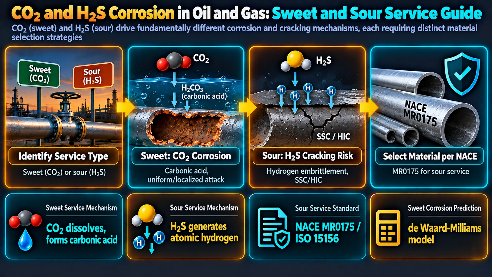
The terms originate from odour: hydrogen sulfide gives sour crude and gas a distinctive rotten-egg smell, while H2S-free production is “sweet” by comparison. Metallurgically, the distinction matters because the two gases drive different corrosion chemistries and, more importantly, different failure consequences. CO2 alone produces a corrosion problem that is primarily about wall-thickness loss and remaining-life calculation. H2S introduces a cracking problem that can cause sudden, brittle failure at stresses and material conditions that would otherwise be considered safe, which is why sour service triggers a distinct materials-qualification regime under industry standards.
CO2 (Sweet) Corrosion Mechanism
Carbonic Acid Formation and the Cathodic Buffering Effect
Dissolved CO2 reacts with water to form carbonic acid, a weak acid that only partially dissociates:
CO2 + H2O ↔ H2CO3          (carbonic acid formation)
H2CO3 ↔ H⁺ + HCO3-        (partial dissociation)

Overall corrosion reaction:
Fe + H2CO3 → FeCO3 + H2     (iron dissolves, siderite scale forms)
Because carbonic acid is only partially dissociated, consuming hydrogen ions at the cathode does not deplete the acid the way it would in a fully dissociated strong acid; instead, more H2CO3 dissociates to replace the consumed H+, buffering the reaction and sustaining a higher effective corrosion rate than a strong acid of the same measured pH would produce. This buffering behaviour, closely related to the general electrochemical framework in corrosion mechanisms, is central to why CO2 corrosion is treated as its own engineering discipline rather than simply “low pH corrosion.”
Iron Carbonate Scale: Protective or Not
The iron carbonate (FeCO3, siderite) formed by the overall reaction can behave in two very different ways. At higher temperatures, typically above roughly 60-70°C depending on water chemistry and supersaturation, FeCO3 tends to precipitate as a dense, adherent scale that substantially slows further corrosion by limiting ion transport to the steel surface. At lower temperatures or under high flow conditions, the scale is often porous, poorly adherent, or removed faster than it forms, leaving the corrosion rate largely unmitigated.
Localized CO2 Attack: Mesa Corrosion
Where a protective scale forms unevenly, or is locally disrupted by flow-induced wall shear stress, exposed patches of bare steel corrode significantly faster than the surrounding scaled regions, producing a distinctive flat-bottomed, stepped attack pattern known as mesa corrosion. This flow-sensitivity means CO2 corrosion assessment must account for pipeline hydraulics and multiphase flow regime, not composition and temperature alone.
Factors Controlling CO2 Corrosion Rate
| Factor | Effect on Corrosion |
|---|---|
| CO2 partial pressure | Higher pCO2 lowers pH and increases corrosion rate |
| Temperature | Increases reaction kinetics, but can also promote protective FeCO3 scale formation above the scaling temperature, sometimes lowering net rate |
| Flow velocity / wall shear stress | Can remove protective scale and increase mass transfer, raising local corrosion rate and promoting mesa attack |
| Organic acids (e.g. acetic acid) | Add corrosivity beyond CO2 alone and can inhibit protective scale formation |
| Trace oxygen ingress | Disproportionately damaging even at very low concentration in otherwise anaerobic systems |
Industry-standard predictive models, most notably the de Waard-Milliams family of correlations, combine these variables to estimate expected CO2 corrosion rates for pipeline and vessel design, though field verification against actual metal-loss inspection data remains standard practice given the number of interacting variables.
H2S (Sour) Corrosion and Hydrogen Damage Mechanisms
H2S corrodes steel through an analogous overall reaction, forming iron sulfide corrosion products (commonly mackinawite or pyrrhotite) instead of iron carbonate. The metallurgically significant difference is not the scale chemistry but what happens to the hydrogen generated at the cathode.
Why H2S Promotes Hydrogen Absorption
Under normal cathodic hydrogen evolution, two adsorbed hydrogen atoms on the steel surface combine and desorb as harmless hydrogen gas. H2S interferes with this recombination step, acting as a hydrogen recombination poison, which leaves a larger population of atomic hydrogen on the surface with nowhere to go but into the steel lattice. This absorbed hydrogen is the root cause of both major sour-service cracking mechanisms, and the same absorption principle underlies the broader family of failures discussed in hydrogen-induced cracking.
Sulfide Stress Cracking (SSC)
Sulfide stress cracking is brittle, hydrogen-assisted cracking of hard or high-strength steel under sustained tensile stress (applied or residual) in a sour environment. Because susceptibility rises sharply with hardness, SSC control in practice means controlling hardness: NACE MR0175/ISO 15156 sets a maximum of approximately 22 HRC for carbon and low-alloy steels in sour service, which in turn governs allowable base metal condition, welding procedure, and post-weld heat treatment requirements, following the same hardness-microstructure relationships covered in quenching and tempering and measured per standard hardness testing methods.
Hydrogen-Induced Cracking (HIC) and SOHIC
Hydrogen-induced cracking occurs when absorbed hydrogen migrates to internal defects, most commonly elongated manganese sulfide inclusions in lower-strength pipeline-grade steels, and recombines there into molecular hydrogen gas. Because this gas is trapped inside the steel, internal pressure builds until it initiates cracks, entirely independent of any externally applied stress. Where these internally initiated cracks link up and reorient under the influence of a superimposed stress field, the result is termed stress-oriented hydrogen-induced cracking (SOHIC), which is of particular concern in weld heat-affected zones. HIC resistance is controlled primarily through steel cleanliness (low sulfur content, inclusion shape control) rather than hardness alone, distinguishing it clearly from SSC as an engineering problem.
NACE MR0175 / ISO 15156 and Sour Service Classification
NACE MR0175, now published jointly with ISO as ISO 15156, is the standard framework the industry uses to classify sour service and specify qualified materials. It defines the H2S partial pressure threshold above which an environment is classified as sour, and sets out hardness limits, permitted material types, and qualification testing requirements (including standardised SSC and HIC test methods) for equipment in that service. Compliance with this standard is typically a contractual and regulatory requirement for oil and gas equipment specification, not merely good practice.
Combined CO2/H2S Service
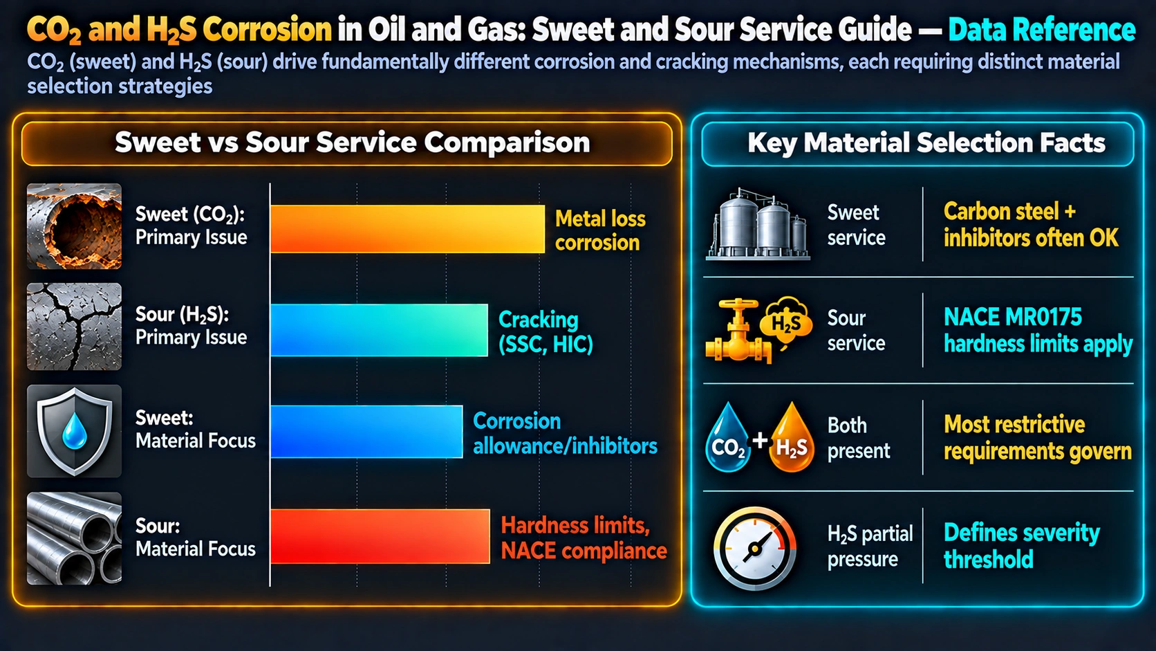
Most produced fluids contain both gases simultaneously, and the ratio between them materially changes which failure mode dominates. Where CO2 partial pressure is much larger than H2S partial pressure, iron carbonate chemistry and general/localized CO2-type attack tend to dominate corrosion behaviour. Where H2S partial pressure is significant relative to CO2, iron sulfide scale formation and hydrogen cracking risk become the controlling design considerations, sometimes even while reducing measured general corrosion rate relative to CO2 alone, because iron sulfide is less soluble and can form protective scale more readily than iron carbonate under some conditions. This is why sour-service design cannot simply be treated as “CO2 corrosion plus a hardness limit” — the two mechanisms interact.
Material Selection Strategy
| Service Condition | Typical Material Approach | Key Consideration |
|---|---|---|
| Low-moderate CO2, no significant H2S | Carbon steel with corrosion allowance, often chemically inhibited | Lowest capital cost; requires ongoing inhibitor injection and monitoring |
| High CO2, high temperature/chloride | 13Cr martensitic stainless or duplex stainless | Improved CO2 resistance; duplex needed where chlorides risk pitting/SCC |
| Sour service, moderate severity | Hardness-controlled carbon/low-alloy steel per NACE MR0175/ISO 15156 | Requires controlled HRC, qualified welding procedures, and PWHT where specified |
| Sour service, high severity / high chloride | 22Cr or 25Cr duplex, or nickel alloys (e.g. Alloy 825, 625) | Highest capital cost; minimal ongoing chemical treatment requirement |
The underlying trade-off, echoed in the broader mild steel vs stainless steel selection guide, is capital cost against ongoing operating cost and risk: inhibited carbon steel defers cost into chemical treatment and monitoring programmes, while corrosion-resistant alloys shift cost upfront in exchange for a largely self-protecting system.
Corrosion Inhibition and Monitoring
Film-forming corrosion inhibitors remain the primary mitigation tool for carbon steel in both sweet and moderately sour service, working by adsorbing onto the steel surface to slow the anodic and cathodic reactions, complementing the general inhibitor mechanisms covered in corrosion inhibitors. Effective inhibition programmes depend on continuous, correctly dosed injection and are supported by corrosion monitoring (coupons, electrical resistance probes, ultrasonic thickness surveys) to verify actual field performance against the corrosion rate assumptions used in design.
Frequently Asked Questions
What is the difference between sweet and sour service in oil and gas?
Why is CO2 corrosion more aggressive than a strong acid at the same pH?
What is mesa corrosion?
Why does H2S cause hydrogen cracking instead of just general corrosion?
What is sulfide stress cracking?
What is hydrogen-induced cracking and how is it different from SSC?
What is NACE MR0175 / ISO 15156?
When is a corrosion-resistant alloy required instead of carbon steel?
Recommended Reference Reading
ASM Handbook, Volume 13C: Corrosion in the Oil and Gas Industry
Dedicated reference on CO2, H2S, and combined-service corrosion mechanisms in upstream and midstream equipment.
View on AmazonFontana’s Corrosion Engineering
Foundational text on weak-acid corrosion chemistry and hydrogen damage mechanisms relevant to sour service.
View on AmazonNACE/ISO 15156 Standards Reference
Reference compilation covering NACE MR0175/ISO 15156 sour service material qualification requirements.
View on AmazonCorrosion Control in the Oil and Gas Industry
Applied reference on inhibitor selection, monitoring, and material strategy for sweet and sour production systems.
View on AmazonDisclosure: MetallurgyZone participates in the Amazon Associates programme. If you purchase through these links, we may earn a small commission at no extra cost to you. This helps support free technical content on this site.
Further Reading
