NACE MR0175 / ISO 15156 Sour Service Explained
NACE MR0175/ISO 15156 is the governing standard for selecting metallic materials resistant to cracking in H2S-containing oil and gas environments. This tutorial explains how the standard defines sour service, the cracking mechanisms it protects against, the material qualification routes for carbon steels and corrosion-resistant alloys, and the practical hardness and welding controls engineers apply to demonstrate compliance.
Key Takeaways
- NACE MR0175 and ISO 15156 are the same harmonized three-part standard; equipment specified as “NACE compliant” means qualified materials selection under this standard.
- Sour service is defined primarily by H2S partial pressure (≥0.3 kPa) at total pressure ≥0.4 MPa, evaluated alongside pH and chloride content for environmental severity.
- Sulfide stress cracking (SSC) is stress-driven and surface-initiated; hydrogen-induced cracking (HIC) is stress-independent and forms internally at inclusions.
- Carbon and low-alloy steels are generally limited to 22 HRC maximum hardness, including weld HAZ, under Part 2 of the standard.
- Corrosion-resistant alloys (Part 3) remain susceptible to SSC above alloy-specific temperature, chloride, and H2S limits and carry separate cold-work restrictions.
- Compliance is demonstrated through standardized test methods (NACE TM0177 for SSC, NACE TM0284 for HIC) plus hardness surveys on welded components.
What Is NACE MR0175/ISO 15156
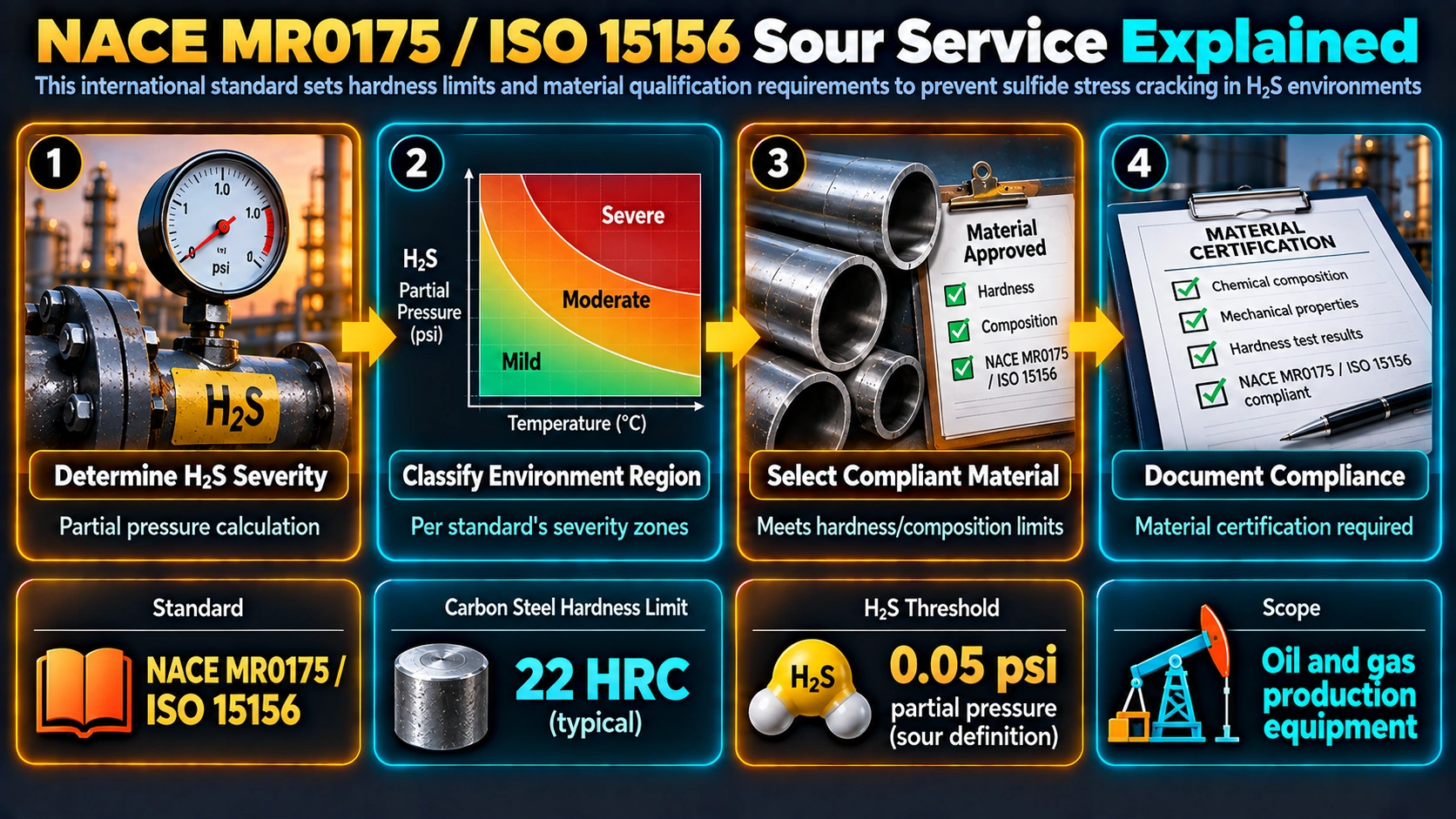
NACE MR0175 originated as a standalone NACE International standard specifying metallic materials resistant to cracking in H2S-containing oil and gas production environments. It was subsequently harmonized with the International Organization for Standardization and republished as the three-part ISO 15156 series, with NACE MR0175 remaining in step with each revision. Equipment specified as “MR0175/ISO 15156 compliant” has had its materials selected and, where required, laboratory-qualified against the standard’s sour service criteria. The standard is referenced directly by equipment product specifications such as API 5CT (casing and tubing), API 6A (wellhead and christmas tree equipment), and API 20B/20C (bolting and fasteners), making it the common materials-selection backbone across upstream and midstream equipment.
Defining Sour Service
ISO 15156-2 classifies an environment as sour, for standard applicability purposes, when the partial pressure of H2S in the gas phase is 0.3 kPa (0.05 psi) or greater at a total absolute pressure of 0.4 MPa (65 psia) or greater. Below this threshold, materials are generally not required to meet the standard’s sour service provisions, though many operators apply more conservative internal criteria for equipment near the boundary or in environments with additional souring risk from reservoir changes or microbiologically influenced sulfate reduction.
Once an environment is classified as sour, its severity for carbon and low-alloy steel selection is further evaluated against H2S partial pressure, in-situ pH, and chloride concentration, placing the application into one of several severity regions (illustrated schematically in Figure 1). Higher severity regions require steels with tighter compositional and processing controls, additional testing, or lower permissible hardness, since increasing H2S partial pressure and decreasing pH both increase the hydrogen charging available to drive cracking.
Cracking Mechanisms the Standard Addresses
Sulfide Stress Cracking (SSC)
Sulfide stress cracking is a form of hydrogen embrittlement in which atomic hydrogen generated by the corrosion reaction with H2S enters the steel and embrittles regions of high hardness or high localized tensile stress, typically the heat-affected zone of a weld or a hard, untempered martensitic microstructure. Cracks are brittle, transgranular, and initiate at the surface where tensile stress (applied, residual, or both) is highest, and can propagate rapidly to failure without warning. See the related discussion on martensite formation for why untempered martensitic microstructures are especially susceptible.
Hydrogen-Induced Cracking (HIC)
Hydrogen-induced cracking does not require applied stress. Atomic hydrogen diffuses into the steel and recombines into molecular hydrogen at internal discontinuities, most commonly elongated manganese sulfide inclusions and centerline segregation bands from continuous casting, building internal pressure that initiates planar cracks parallel to the rolling direction. These cracks can link between rolling planes in a stepwise pattern. Susceptibility is controlled primarily through steel cleanliness (low sulfur content, inclusion shape control, calcium treatment) rather than hardness alone.
Stress-Oriented Hydrogen-Induced Cracking (SOHIC)
SOHIC combines features of both mechanisms: arrays of small HIC-type cracks link together in a direction roughly perpendicular to the applied or residual stress field, commonly observed adjacent to weld heat-affected zones where residual stress is highest, producing a more damaging crack path than isolated HIC alone.
Material Qualification Under Part 2: Carbon and Low-Alloy Steels
Hardness Control
ISO 15156-2 generally limits carbon and low-alloy steel hardness to 22 HRC maximum, applied to base metal, weld metal, and heat-affected zone, since hardness above this threshold correlates with untempered or under-tempered martensite that is significantly more susceptible to SSC. Some product forms and specific steel types carry alternative or additional limits defined in the standard’s compositional and processing tables, so the applicable table must be checked against the specific product form rather than assuming a single blanket value.
SSC Qualification Testing
NACE TM0177 defines four standardized test methods for demonstrating SSC resistance in a sour test solution:
Method A  - uniaxial tensile specimen, pass/fail at specified stress
Method B  - bent-beam specimen, pass/fail at specified stress
Method C  - C-ring specimen, pass/fail at specified stress
Method D  - double cantilever beam, threshold stress intensity K_ISSC
HIC Qualification Testing
NACE TM0284 exposes unstressed flat specimens to a standard sour solution (commonly Solution A or Solution B) and evaluates sectioned specimens metallographically for three ratios used to judge acceptability against the governing equipment specification.
CLR (Crack Length Ratio)    = Σ(crack length) / specimen length × 100%
CTR (Crack Thickness Ratio) = Σ(crack length × through-thickness) / (length × thickness) × 100%
CSR (Crack Sensitivity Ratio) = Σ(crack length × crack width) / (length × thickness) × 100%
Material Qualification Under Part 3: Corrosion-Resistant Alloys
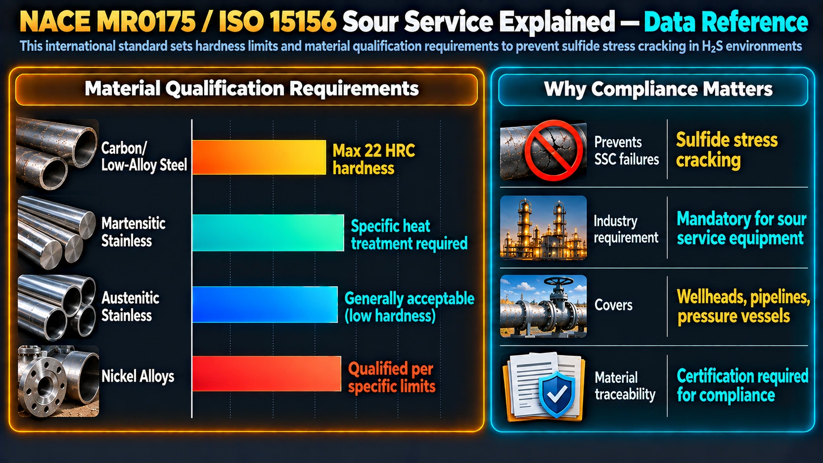
ISO 15156-3 covers corrosion-resistant alloys (CRAs), including martensitic, ferritic, austenitic, and duplex stainless steels, and nickel-based alloys. CRAs remain susceptible to SSC above material- and environment-specific combinations of temperature, chloride concentration, H2S partial pressure, and elemental sulfur presence; the standard provides qualified limits by alloy family rather than a single hardness threshold as used for carbon steels. Key considerations include:
Cold Work Limits
Cold-worked CRAs (for example cold-drawn duplex stainless tubing) develop elevated strength that increases SSC susceptibility, so the standard restricts maximum permissible yield strength or hardness as a function of cold-work level and alloy grade.
Welding of CRAs
Welding introduces a cast, potentially segregated microstructure and residual stress in the CRA weld metal and HAZ. Qualification testing for welded CRA components uses the same TM0177 methods, most commonly Method A or D, applied to representative welded specimens rather than base metal alone, since the weld region typically governs SSC resistance.
Comparing Sour Service Material Classes
| Material class | Standard part | Primary control | Typical qualification test |
|---|---|---|---|
| Carbon / low-alloy steel | Part 2 | Hardness ≤22 HRC, HIC-resistant steel chemistry | TM0177 (SSC), TM0284 (HIC) |
| Martensitic stainless (e.g. 13Cr) | Part 3 | Tempered hardness, temperature limit | TM0177 Method A or D |
| Duplex / super duplex stainless | Part 3 | Cold-work limit, chloride/temperature envelope | TM0177 Method D (K_ISSC) |
| Austenitic stainless | Part 3 | Cold-work / yield strength limit | TM0177 Method C or D |
| Nickel-based alloys | Part 3 | Alloy-specific environmental limits | TM0177 Method D |
Welding and Heat-Affected Zone Control
The weld heat-affected zone is frequently the highest-hardness region of a fabricated component due to the rapid thermal cycling during welding, and is where SSC most often initiates in otherwise-qualified base metal. Welding procedure qualification for sour service equipment specifies preheat and interpass temperature control, controlled heat input, and, where the qualified welding procedure requires it, post-weld heat treatment to temper untempered HAZ martensite. Hardness surveys across the weld cap, HAZ, and base metal are performed on production welds or procedure qualification records to verify the 22 HRC limit is met, consistent with the principles covered in quenching and tempering practice.
Industrial Application and Commercial Relevance
NACE MR0175/ISO 15156 compliance is a mandatory procurement requirement for wellheads, christmas trees, valves, flowlines, separators, and pressure vessels in H2S-containing service, and is referenced directly within API 5CT, API 6A, and related product specifications as the basis for sour service product specification levels (PSL). Non-compliant materials selection in sour service is a leading root cause of premature, brittle in-service failures, making correct standard interpretation a significant commercial and safety issue for equipment suppliers, EPC contractors, and operating companies across upstream and midstream oil and gas.
Frequently Asked Questions
What is the difference between NACE MR0175 and ISO 15156?
What partial pressure of H2S defines sour service?
What is the maximum hardness allowed for carbon steel in sour service?
What is the difference between SSC and HIC?
What test methods qualify materials against sulfide stress cracking?
How is a material qualified against hydrogen-induced cracking?
Do corrosion-resistant alloys still need sour service qualification?
Does welding affect NACE MR0175/ISO 15156 compliance?
Recommended Reference Reading
NACE Corrosion Engineer’s Reference Book
Standards-oriented reference covering sour service classification and qualification testing.
View on AmazonUhlig’s Corrosion Handbook
Comprehensive mechanism reference covering hydrogen damage and sulfide stress cracking.
View on AmazonHydrogen Embrittlement: Prevention and Control
Focused reference on hydrogen damage mechanisms relevant to SSC and HIC.
View on AmazonWelding Metallurgy and Weldability of Nickel-Base Alloys
Reference for CRA welding behaviour relevant to Part 3 qualification.
View on AmazonDisclosure: MetallurgyZone participates in the Amazon Associates programme. If you purchase through these links, we may earn a small commission at no extra cost to you. This helps support free technical content on this site.
Further Reading
