Corrosion Monitoring Techniques for Pipelines: A Complete Engineering Guide
Pipeline corrosion monitoring converts an invisible, time-dependent degradation mechanism into measurable data that asset-integrity engineers can act on before a wall-loss defect becomes a leak or rupture. This guide reviews the intrusive, non-intrusive, and in-line inspection techniques used across oil, gas, and water pipelines, explains how each method infers corrosion rate or wall condition, and sets out how to combine techniques into a defensible, standards-based monitoring strategy.
Key Takeaways
- Intrusive methods (coupons, ER probes, LPR probes) give point measurements of corrosion rate at a monitoring location and are the backbone of process-side trending.
- Non-intrusive and in-line methods (UT, guided wave UT, MFL/UT pigs) measure actual remaining wall thickness directly on the pipe, independent of assumptions about the monitoring location representing the whole line.
- LPR probes give near-real-time corrosion rate in conductive electrolytes; ER probes work in any fluid but average corrosion rate over the exposure interval.
- Cathodic protection monitoring (pipe-to-soil potential, close interval survey) verifies external corrosion control on buried and subsea steel pipelines per NACE/AMPP SP0169.
- Hydrogen probes provide an indirect, continuous measure of internal corrosion activity in H2S-containing sour service.
- No single technique covers all corrosion mechanisms and locations; a risk-based inspection (API 580/581) framework combines multiple methods against known threat mechanisms.
Why Pipeline Corrosion Monitoring Matters

Pipeline steels lose wall thickness through internal mechanisms (CO2 sweet corrosion, H2S sour corrosion, microbiologically influenced corrosion, erosion-corrosion at bends and welds) and external mechanisms (soil-side galvanic and stray-current corrosion, coating disbondment, near-neutral and high-pH stress corrosion cracking). Monitoring converts these mechanisms into trackable data so that operators can adjust chemical inhibition, cathodic protection output, or inspection intervals before a corrosion allowance is exhausted. Under integrity management frameworks such as API 570 (piping) and ASME B31.8S (gas transmission), documented monitoring data is also the primary evidence base for re-rating, run/repair/replace decisions, and remaining-life calculations.
Corrosion Mechanisms Relevant to Pipeline Monitoring
Selecting a monitoring technique starts with the governing degradation mechanism, since each method is sensitive to a different failure mode.
Internal Mechanisms
CO2 corrosion produces general or mesa-type wall loss governed by partial pressure, temperature, and water chemistry; H2S sour corrosion produces iron sulfide scale and can drive sulfide stress cracking and hydrogen-induced cracking in susceptible quenched and tempered line pipe steels; microbiologically influenced corrosion produces localized pitting beneath biofilm deposits, typically at low points and dead legs.
External Mechanisms
External corrosion on buried lines is controlled primarily by coating condition and cathodic protection coverage. Where the coating disbonds and shields cathodic protection current, near-neutral-pH stress corrosion cracking can initiate from shallow pits and grow as colonies of parallel cracks aligned with the pipe axis, driven by cyclic pressure loading. Refer to the eutectoid transformation background for how line-pipe microstructure influences cracking susceptibility.
Intrusive (Direct) Monitoring Methods
Corrosion Coupons
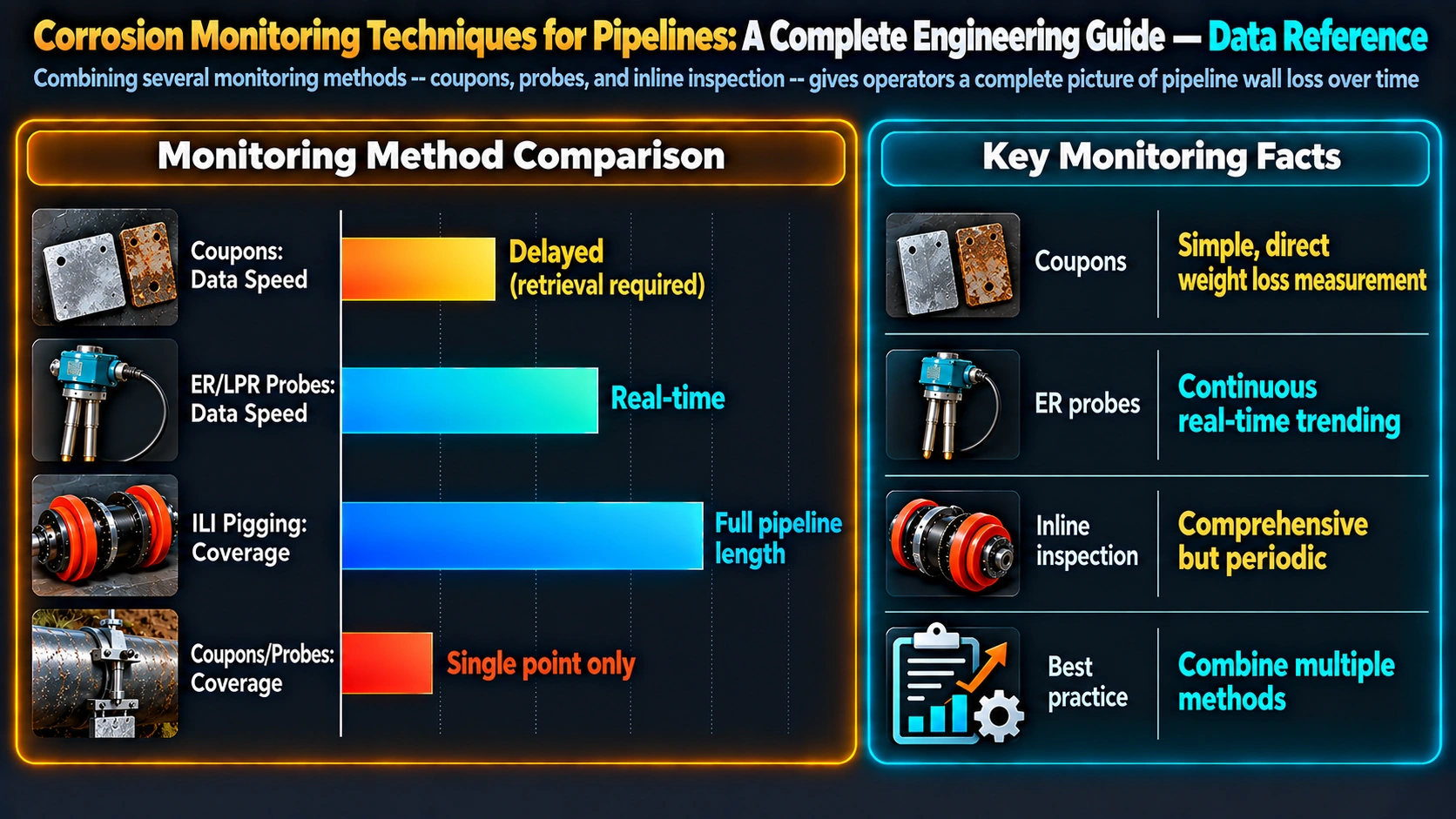
A coupon of known alloy, geometry, and mass is exposed to the process stream on a retrievable holder, pulled after a fixed interval, cleaned per ASTM G1, and weighed. Metal loss is converted to a corrosion rate. Coupons are inexpensive and give a direct gravimetric measurement, but the result is an average over the exposure period and gives no information on rate variation within that interval.
Corrosion rate (mpy) = (K × W) / (A × T × D)

K = 3.45 × 10⁶  (constant for mpy units)
W = mass loss, g
A = exposed surface area, cm²
T = exposure time, hours
D = metal density, g/cm³
Electrical Resistance (ER) Probes
An ER probe exposes a thin metallic element of known initial cross-section to the process. As the element corrodes, its cross-section shrinks and its electrical resistance rises proportionally. The instrument reports metal loss continuously and works in gases, non-conductive hydrocarbons, and multiphase flow where electrochemical probes cannot function, but the technique has a slower response than LPR because it relies on integrated metal loss rather than instantaneous current.
Linear Polarization Resistance (LPR) Probes
LPR probes apply a small polarization (typically ±10-20 mV) around the corrosion potential and measure the resulting current, giving the polarization resistance Rp. Instantaneous corrosion current density is obtained from the Stern-Geary relationship, giving a corrosion rate reading within minutes. LPR requires a continuous conductive electrolyte and is unsuitable for gas or oil-continuous streams.
i_corr = B / R_p

B = Stern-Geary constant (typically 0.026 V for active corrosion,
    0.052 V for passive systems)
R_p = polarization resistance, ohm·cm²
Galvanic (ZRA) and Electrical Field Signature Probes
Zero-resistance ammetry probes measure galvanic current between dissimilar electrodes to flag localized pitting tendency, while electrical field signature technology maps current distribution across a fixed pipe spool to detect localized wall thinning without removing the spool from service.
Hydrogen Probes
In H2S sour service, atomic hydrogen generated by the cathodic reaction diffuses through the steel wall. A hydrogen probe measures this permeation flux, either by pressure buildup in a sealed access-fitting probe or by vacuum/electrochemical hydrogen patch methods, giving a continuous indirect indicator of internal corrosion activity and hydrogen-induced cracking risk relevant to sour-service line pipe qualified per NACE MR0175/ISO 15156.
Non-Intrusive and External Monitoring Methods
Ultrasonic Thickness Gauging
Handheld or permanently mounted ultrasonic transducers measure remaining wall thickness directly at fixed grid points, typically at corrosion-prone locations such as elbows, tees, and low points. Permanently installed wireless UT sensors allow scheduled automatic logging without personnel access, useful for insulated or difficult-to-reach lines.
Guided Wave Ultrasonic Testing
Guided wave UT launches a low-frequency torsional or longitudinal wave along the pipe axis from a single collar, screening tens of metres in each direction. It is a screening tool for locating gross anomalies under insulation, at sleeve crossings, or at road/rail crossings; detected indications are then sized with conventional UT or radiography.
Radiographic Testing
Radiography gives a direct image of wall condition and is particularly effective for corrosion under insulation where UT contact is difficult, though it requires radiation safety controls and is slower and more costly per point than UT.
Fiber-Optic Distributed Sensing
Distributed temperature and acoustic sensing fiber run along the pipeline can detect leaks and, in some configurations, strain anomalies associated with wall loss or third-party interference over the full pipeline length in near real time.
In-Line Inspection (ILI)
In-line inspection tools (“smart pigs”) travel through the pipeline with the product flow and log wall condition over the entire inspected length, giving the most complete dataset of any monitoring method for piggable lines.
Magnetic Flux Leakage (MFL)
MFL tools magnetize the pipe wall and detect flux leakage at areas of reduced wall thickness using an array of sensors, providing good detection of general and localized metal loss at moderate sizing accuracy.
Ultrasonic In-Line Inspection
Ultrasonic ILI tools couple through the liquid product to measure wall thickness directly, giving higher sizing accuracy than MFL for metal loss and the ability to detect crack-like features when configured with angled shear-wave sensors, at the cost of requiring a liquid-filled, relatively clean line.
Cathodic Protection Monitoring
For buried and subsea steel pipelines, cathodic protection is the primary external corrosion control, and its effectiveness is verified rather than assumed.
Pipe-to-Soil Potential Surveys
A reference electrode (typically copper-copper sulfate) placed on the soil surface above the pipe measures pipe-to-soil potential at test stations. NACE/AMPP SP0169 specifies a protection criterion of -850 mV (instant-off) relative to the reference electrode as the standard benchmark for adequate cathodic protection on carbon steel.
Close Interval Survey (CIS)
A close interval survey walks the pipeline route logging pipe-to-soil potential at close, regular spacing (typically 1 to 3 metres), identifying localized areas of coating damage or insufficient current that a widely spaced test-station survey would miss.
Comparing Pipeline Corrosion Monitoring Techniques
| Technique | Measures | Response time | Coverage | Typical application |
|---|---|---|---|---|
| Corrosion coupon | Average mass loss corrosion rate | Weeks to months | Point | Baseline trending, any fluid |
| ER probe | Cumulative metal loss | Days to weeks | Point | Gas, oil, multiphase streams |
| LPR probe | Instantaneous corrosion current | Minutes | Point | Conductive aqueous streams |
| Hydrogen probe | Hydrogen permeation flux | Hours to days | Point | Sour (H2S) service |
| Ultrasonic thickness gauge | Remaining wall thickness | Instant per point | Point / grid | Fixed inspection points |
| Guided wave UT | Gross wall loss indication | Instant per collar | 10s of metres | Under-insulation, crossings |
| MFL / UT in-line inspection | Wall thickness / metal loss profile | Days to process run | Full pipeline length | Piggable transmission lines |
| CP potential / CIS survey | External corrosion protection level | Instant per point | Route length | Buried / subsea steel pipe |
Industrial Applications and Standards
Monitoring data feeds directly into fitness-for-service and remaining-life assessments. API 570 governs in-service piping inspection intervals, ASME B31.8S structures integrity management for gas transmission systems around identified threats, and NACE/AMPP SP0169 sets the cathodic protection criteria referenced above. Risk-based inspection under API 580/581 combines probability of failure, derived from monitored corrosion rate and mechanism data, with consequence of failure to prioritize which segments receive which monitoring technique and at what frequency, concentrating resources on the highest-risk sections rather than applying uniform coverage across an entire system.
Selecting a Monitoring Strategy
An effective programme rarely relies on one technique. A typical strategy pairs continuous point monitoring (ER or LPR probes, hydrogen probes in sour service) for process-side trending, periodic in-line inspection for full-length wall condition on piggable lines, and cathodic protection surveys for external corrosion control on buried sections, with guided wave UT and radiography used selectively at inaccessible or insulated locations that ILI or fixed probes cannot cover. The governing corrosion mechanism, line piggability, and consequence of failure at each segment determine which combination is justified.
Frequently Asked Questions
What is the most accurate method for monitoring pipeline corrosion?
What is the difference between ER probes and LPR probes?
How often should pipeline corrosion coupons be pulled?
What is guided wave ultrasonic testing used for on pipelines?
How does cathodic protection monitoring detect corrosion risk?
What causes stress corrosion cracking in buried pipelines?
Can hydrogen probes detect internal corrosion in sour service?
How is risk-based inspection used to plan a pipeline monitoring programme?
Recommended Reference Reading
Corrosion Engineering (Fontana)
Classic electrochemistry and corrosion mechanism reference underpinning ER/LPR probe theory.
View on AmazonPipeline Corrosion Control Handbook
Practical reference on cathodic protection design, CIS surveys, and coating assessment.
View on AmazonNACE Corrosion Engineer’s Reference Book
Standards-oriented reference covering monitoring techniques, criteria, and inspection planning.
View on AmazonUhlig’s Corrosion Handbook
Comprehensive materials-and-mechanism handbook for sour service and localized corrosion review.
View on AmazonDisclosure: MetallurgyZone participates in the Amazon Associates programme. If you purchase through these links, we may earn a small commission at no extra cost to you. This helps support free technical content on this site.
Further Reading
