TRIP and TWIP Steels: Microstructure, Stacking Fault Energy, Work Hardening Mechanisms, and Automotive Applications
TRIP (TRansformation-Induced Plasticity) and TWIP (TWinning-Induced Plasticity) steels are the two most mechanistically distinctive families within the advanced high-strength steel (AHSS) portfolio. Both exploit austenite instability — TRIP through strain-induced phase transformation to martensite, TWIP through the nucleation of mechanical deformation twins — to maintain an exceptionally high work hardening rate across large strains, delivering strength-ductility products that conventional ferritic, martensitic, or even dual-phase steels cannot match. This guide covers the physical metallurgy foundations, alloy design logic, thermodynamic and kinetic frameworks governing each mechanism, processing routes, forming behaviour, and the automotive structural applications where these grades are displacing heavier conventional steel.
Key Takeaways
- The operative deformation mechanism — strain-induced martensite (TRIP), mechanical twinning (TWIP), or dislocation glide — is controlled by stacking fault energy (SFE), which is a function of composition and temperature.
- First-generation TRIP-assisted multiphase steels contain a ferrite-bainite matrix with 5–15 vol% metastable retained austenite; silicon or aluminium suppresses carbide precipitation during bainitic transformation to enrich austenite in carbon.
- TWIP steels (15–30 wt% Mn) are fully austenitic at room temperature; mechanical twins act as dynamic Hall-Petch boundaries, sustaining work hardening rates of 2000–4000 MPa over strains exceeding 50%.
- The SFE window for TWIP behaviour in Fe-Mn-C alloys is approximately 20–45 mJ/m²; below 20 mJ/m² the TRIP mechanism operates; above 45 mJ/m² dislocation glide dominates with no twinning.
- Third-generation AHSS grades (Q&P steels, medium-Mn TRIP, TRIP-maraging) target the property gap between first- and second-generation AHSS: tensile strengths 1000–1600 MPa with elongations of 20–40%.
- TWIP steels face production challenges including high-Mn steelmaking complexity, delayed hydrogen fracture, and resistance-spot-welding difficulties that have limited their mass-production adoption to date.
Stacking Fault Energy: The Master Variable in TRIP and TWIP Steels
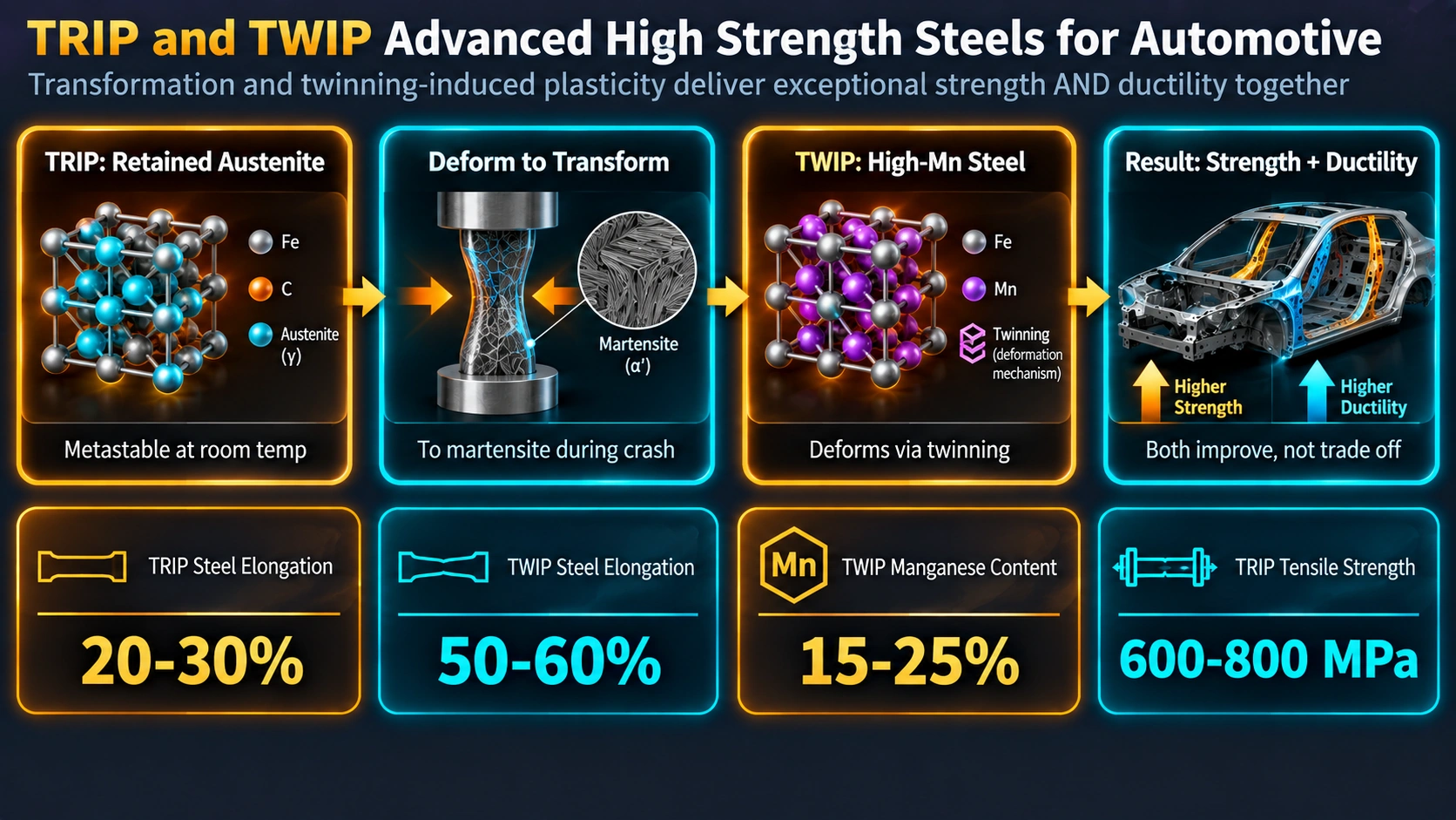
Stacking fault energy (SFE) is the excess free energy per unit area of a stacking fault — a layer of material with incorrect close-packed stacking sequence, equivalent to two atomic layers of HCP structure embedded within the FCC austenite matrix. It governs the separation distance between the two partial (Shockley) dislocations that bound an extended dislocation, and therefore determines how easily the partials can be recombined for cross-slip versus how readily the fault widens to nucleate a twin or an HCP embryo (which is the precursor to the martensite transformation in TRIP steels).
SFE Values and Mechanism Boundaries
For iron-manganese-carbon austenitic steels, the experimentally and computationally established boundaries are:
| SFE Range (mJ/m²) | Deformation Mechanism | Effect | Typical Steel Family |
|---|---|---|---|
| < 18–20 | Strain-induced γ → ε → α’ martensitic transformation | TRIP effect — progressive hardening by martensite formation | TRIP-assisted multiphase, 301 SS, retained-austenite grades |
| 20–45 | Mechanical deformation twinning | TWIP effect — dynamic Hall-Petch by twin subdivision of grains | Fe-(15–30)Mn-C-Al TWIP steels |
| > 45 | Planar and wavy dislocation glide | Conventional work hardening — no twinning, no transformation | 316L, 310S, Al-containing austenitic grades |
Composition Dependence of SFE
SFE in Fe-Mn-C-Al-Si alloys is described by several CALPHAD-based models. A widely used empirical expression for Fe-Mn-C alloys (Olson-Cohen, Curtze-Kuokkala) relates SFE to the molar Gibbs energy of the γ → ε transformation:
SFE = 2ρ ΔGγ→ε + 2σγ/ε

Where:
  ρ       = molar surface density of {111} planes = √3/(4a² N_A)  [mol/m²]
  ΔGγ→ε = molar Gibbs energy change γ → ε (function of T, composition)
  σγ/ε  = γ/ε interfacial energy ≈ 5–15 mJ/m²

Composition effects (approximate increments at 25°C):
  Each +1 wt% Mn:  +1.5 to +2.0 mJ/m²
  Each +1 wt% C:   +25 to +40 mJ/m²
  Each +1 wt% Al:  +5 to +7  mJ/m²
  Each +1 wt% Si:  −5 to −7  mJ/m²
  Each +1 wt% Cr:  −1 to −2  mJ/m²
Temperature lowers SFE in most Fe-Mn-C compositions, which is why some alloys that show twinning (TWIP) at ambient temperature shift to TRIP behaviour at sub-zero temperatures. This is directly relevant to automotive crash scenarios — the dynamic loading of automotive structures at low temperatures may activate TRIP in alloys designed as TWIP grades at room temperature. The temperature sensitivity also explains why the formability of TRIP-assisted steels improves at elevated forming temperatures, as higher SFE suppresses the transformation and allows more ductile flow before hardening commences.
TRIP-Assisted Multiphase Steels: Alloy Design and Microstructure
The term “TRIP steel” in commercial usage covers two distinct alloy families. Classical first-generation TRIP-assisted steels are low-alloy multiphase steels with a ferrite-bainite matrix and a minority fraction of metastable retained austenite. These are distinct from fully austenitic TRIP stainless steels (e.g., 301, 201, metastable 304) that also exploit strain-induced martensite but from a different microstructural baseline. This section focuses on the automotive-grade TRIP-assisted multiphase family.
Phase Constitution
The equilibrium microstructure of a correctly processed TRIP-assisted steel at room temperature consists of four phases:
- Polygonal ferrite (α): 50–70 vol%, provides ductility and the low-yield-strength matrix that allows large macroscopic strains. Ferrite carbon content is very low (<0.01 wt%).
- Bainite (αb): 20–30 vol%, provides strength via its dislocation sub-structure and acts as a carbon-rejection source to enrich adjacent retained austenite. Carbon content of bainitic ferrite is approximately 0.03–0.08 wt%.
- Retained austenite (γR): 5–15 vol%, metastably maintained at room temperature by carbon enrichment (typically 1.0–1.5 wt% C in the austenite). This is the phase that transforms to martensite during deformation.
- Martensite (α’): 0–5 vol% prior to deformation (as-processed); volume fraction increases progressively during plastic straining as γR transforms.
Role of Silicon and Aluminium
The critical enabling alloying addition for TRIP-assisted steels is silicon (typically 1.0–1.8 wt%) or aluminium (0.5–2.0 wt%), both of which have very low solubility in cementite (Fe₃C) and therefore strongly retard carbide precipitation from austenite during bainitic transformation. Without this suppression, the carbon rejected from bainitic ferrite would precipitate as interlath carbides rather than enriching the residual austenite, making austenite stabilisation thermodynamically impossible. The critical difference between Si and Al as carbide suppressors is their effect on the galvanising reaction: silicon forms a tenacious SiO₂ surface oxide that severely impairs hot-dip zinc adhesion. Al substitutes the suppression role without forming adherent surface oxides, enabling galvanised TRIP steel production. Modern automotive TRIP grades use Si-Al co-additions or fully Al-substituted compositions to balance processability and surface quality.
Typical Compositions
| Grade | C (%) | Mn (%) | Si (%) | Al (%) | Rp0.2 (MPa) | Rm (MPa) | A80 (%) | RA vol% |
|---|---|---|---|---|---|---|---|---|
| TRIP 600 | 0.20 | 1.5 | 1.5 | — | 340 | 600 | 30 | 8–12 |
| TRIP 700 | 0.22 | 1.6 | 1.6 | — | 400 | 700 | 25 | 7–10 |
| TRIP 800 | 0.23 | 1.7 | 0.4 | 1.5 | 450 | 800 | 20 | 5–9 |
| TRIP-Al 800 | 0.20 | 1.8 | 0.2 | 2.0 | 460 | 820 | 22 | 8–12 |
Processing Route: Intercritical Annealing and Bainitic Hold
The multiphase microstructure is produced by a two-stage thermal cycle on the continuous annealing line or hot-dip galvanising line:
- Intercritical annealing (IA): The cold-rolled strip is heated to and held in the α+γ two-phase region (typically 780–830°C for 1–3 minutes), establishing the desired ferrite/austenite phase fractions. The austenite formed intercritically is enriched in carbon (typically 0.35–0.55 wt% C at this stage) relative to the bulk composition.
- Rapid cooling: Strip is quenched to the bainitic transformation temperature (typically 350–500°C) at >30°C/s to avoid pearlite formation.
- Bainitic hold (isothermal transformation): Strip is held at 350–500°C for 30–300 seconds. Bainite forms progressively; carbon is rejected from bainitic ferrite into untransformed austenite, enriching its carbon content to the 1.0–1.5 wt% level required for room-temperature metastability. Silicon/aluminium prevents carbide precipitation during this stage.
- Final cooling to room temperature: The carbon-enriched austenite is now sufficiently stable (Ms below room temperature) to survive quenching and remain as retained austenite.
This processing is thermodynamically related to the Quench and Partition (Q&P) process used for third-generation AHSS — the key difference being that Q&P uses a martensite-start quench followed by a partitioning hold rather than a bainitic isothermal hold. The Ms temperature calculation and its dependence on austenite carbon content is described in the martensite formation and Ms prediction article.
Retained Austenite Stability and the Olson-Cohen Model
The stability of retained austenite against strain-induced transformation governs the TRIP kinetics and thereby the shape of the stress-strain curve. Too-stable austenite transforms late in the deformation, wasting the TRIP effect in a forming window already past peak strain; too-unstable austenite transforms early, producing a pronounced hardening peak that promotes premature localisation (necking) in deep-drawing operations.
The Olson-Cohen model describes martensite nucleation kinetics at shear-band intersections:
f_m = 1 − exp[−β{1 − exp(−αε)}ⁿ]

Where:
  f_m = volume fraction of strain-induced martensite
  ε   = equivalent plastic strain
  α   = shear-band formation rate (increases with decreasing T, decreasing SFE)
  β   = probability of martensite nucleation at shear-band intersections
  n   = geometric factor, commonly taken as 4.5 (Olson-Cohen)

The model predicts a sigmoidal f_m vs ε curve.
At low strain: few shear bands, low f_m.
At intermediate strain: rapid martensite formation as intersections multiply.
At high strain: saturation as residual austenite becomes increasingly stable
               (carbon-partitioned regions are less susceptible).
Austenite stability is enhanced by increasing carbon content, reducing grain size, and increasing the Ms-T margin (T < Ms favours spontaneous transformation; T > Ms by a larger margin requires more mechanical driving force). Grain size effects follow a Hall-Petch type relationship for shear-band formation probability. For the relationship between austenite stability and the broader martensite transformation framework, see the martensite formation article and the discussion of retained austenite in quenching and tempering.
TWIP Steels: Alloy Design and the Twinning Mechanism
TWIP steels are fully austenitic iron-manganese alloys in which mechanical deformation twins — rather than martensite — are the primary plasticity carriers at moderate-to-large strains. The extraordinarily high work hardening rate that results from progressive twin formation delivers strength-ductility products (UTS × A) in the range of 40,000–70,000 MPa·% — two to four times those achievable with conventional HSLA or dual-phase steels.
Composition Design
The foundational TWIP composition window in binary Fe-Mn alloys is approximately 15–30 wt% Mn. Below 15% Mn, the alloy is insufficiently stable and transforms to martensite at room temperature (TRIP territory). Above 30% Mn, cost increases prohibitively and the SFE may enter the pure glide regime depending on carbon content. Carbon additions of 0.3–0.8 wt% are standard and serve three purposes: raising SFE into the TWIP window, providing solid-solution strengthening of the austenite, and stabilising austenite against martensite formation at low temperatures (important for crash scenarios). Aluminium at 1.0–3.0 wt% also raises SFE (as calculated above) and provides density reduction — each 1 wt% Al reduces steel density by approximately 0.1 g/cm³, contributing to lightweighting alongside strength. Silicon at <0.5 wt% can be tolerated but higher Si shifts SFE below the TWIP window and promotes TRIP or even embrittling ε-martensite formation.
The Dynamic Hall-Petch Effect
The mechanism that sustains high work hardening rates in TWIP steels is the dynamic Hall-Petch effect, formalised by Bouaziz and Guelton. As deformation proceeds, mechanical twins nucleate on {111} planes along <112> directions and grow to span entire grains. Each twin boundary is a low-angle interface that acts as a barrier to subsequent dislocation motion in exactly the same way as a grain boundary. The effective mean free path for dislocation slip λ decreases continuously with twin volume fraction ftwin:
1/λ = 1/d_grain + f_twin/(e_twin)

Where:
  d_grain = original grain diameter
  f_twin  = volume fraction of deformation twins (increases with strain)
  e_twin  = mean twin thickness (≈ 30–100 nm in typical TWIP steels)

Work hardening rate dσ/dε ≅ M α_T μ b / λ

Where:
  M     = Taylor factor (≈ 3.06 for random texture)
  α_T   = dislocation interaction coefficient (≈ 0.35)
  μ     = shear modulus (≈ 80 GPa for Fe-Mn austenite)
  b     = Burgers vector (≈ 0.254 nm)

Result: dσ/dε remains high (2000–4000 MPa) across strains of 30–70%,
        compared to rapid saturation in conventional austenite (dσ/dε → ~0 by ε ≈ 0.3).
Key Commercial TWIP Compositions
| Alloy | C (%) | Mn (%) | Al (%) | SFE (mJ/m²) | Rp0.2 (MPa) | Rm (MPa) | A (%) |
|---|---|---|---|---|---|---|---|
| Fe-22Mn-0.6C | 0.6 | 22 | — | ≈25 | 360 | 1000 | 65 |
| Fe-18Mn-0.6C-1.5Al | 0.6 | 18 | 1.5 | ≈35 | 400 | 1050 | 60 |
| Fe-25Mn-3Al-3Si | 0.3 | 25 | 3.0 | ≈30 | 450 | 950 | 55 |
| X-IP 1000 (Arcelor) | 0.8 | 28 | — | ≈20 | 580 | 1100 | 45 |
Third-Generation AHSS: Bridging the Strength-Ductility Gap
First-generation AHSS (dual-phase, TRIP-assisted, MART) and second-generation AHSS (TWIP) define two clusters in strength-ductility space. First-generation grades reach 500–1200 MPa tensile strength but elongation of 5–25%. Second-generation TWIP grades achieve exceptional elongation (>40%) but at lower strength levels (700–1200 MPa) combined with high cost and processing complexity. Third-generation AHSS targets tensile strengths of 1000–1600 MPa with elongations of 20–40% at alloy costs closer to first-generation grades.
Quench and Partition (Q&P) Steels
Q&P processing, developed by Speer et al. (2003), achieves TRIP-like microstructures with higher martensite fractions. The steel is quenched to a temperature TQ between Ms and Mf to produce a controlled martensite fraction, then held at a partitioning temperature TP (which may equal TQ or be higher) to allow carbon to diffuse from supersaturated martensite into retained austenite. This carbon enrichment raises the austenite Ms below room temperature, preserving it. The resulting microstructure of tempered martensite plus carbon-stabilised retained austenite (typically 10–20 vol%) delivers tensile strengths of 1200–1600 MPa with elongations of 12–20%. Q&P 980 and Q&P 1180 are commercially available from several major steelmakers for automotive structural applications.
Medium-Manganese TRIP Steels
Medium-Mn steels (4–12 wt% Mn, 0.05–0.3 wt% C) intercritically annealed produce ultrafine-grained (<2 μm) austenite-ferrite mixtures with 20–70 vol% austenite retained at room temperature by Mn partitioning. The ultrafine grain size raises yield strength through Hall-Petch hardening, the retained austenite provides TRIP-assisted elongation, and the lower Mn content reduces cost relative to TWIP. Tensile strengths of 1000–1400 MPa with elongations of 20–35% place medium-Mn grades squarely in the third-generation target window. Lüders band propagation in medium-Mn steels (due to the pronounced yield point phenomenon from Mn-C interactions at austenite-ferrite interfaces) is an active area of research, as inhomogeneous deformation produces surface defects in automotive panels.
AHSS Generation Overview
| Generation | Key Grades | Mechanism | Rm (MPa) | A (%) | Alloy Cost |
|---|---|---|---|---|---|
| 1st Gen | DP 590–1180, TRIP 600–800, MART 1200–1700, CP 800–1000 | Hard phase martensite, bainite; TRIP via RA | 500–1700 | 3–25 | Low |
| 2nd Gen | TWIP 700–1100, L-IP, SIP | Mechanical twinning; fully austenitic | 700–1200 | 40–80 | High (15–30% Mn) |
| 3rd Gen | Q&P 980/1180, Medium-Mn TRIP, TRIP-maraging, XIP | Q&P carbon partitioning; ultrafine austenite TRIP | 1000–1600 | 15–40 | Medium |
Forming Behaviour and Automotive Structural Applications
Forming Characteristics of TRIP Steels
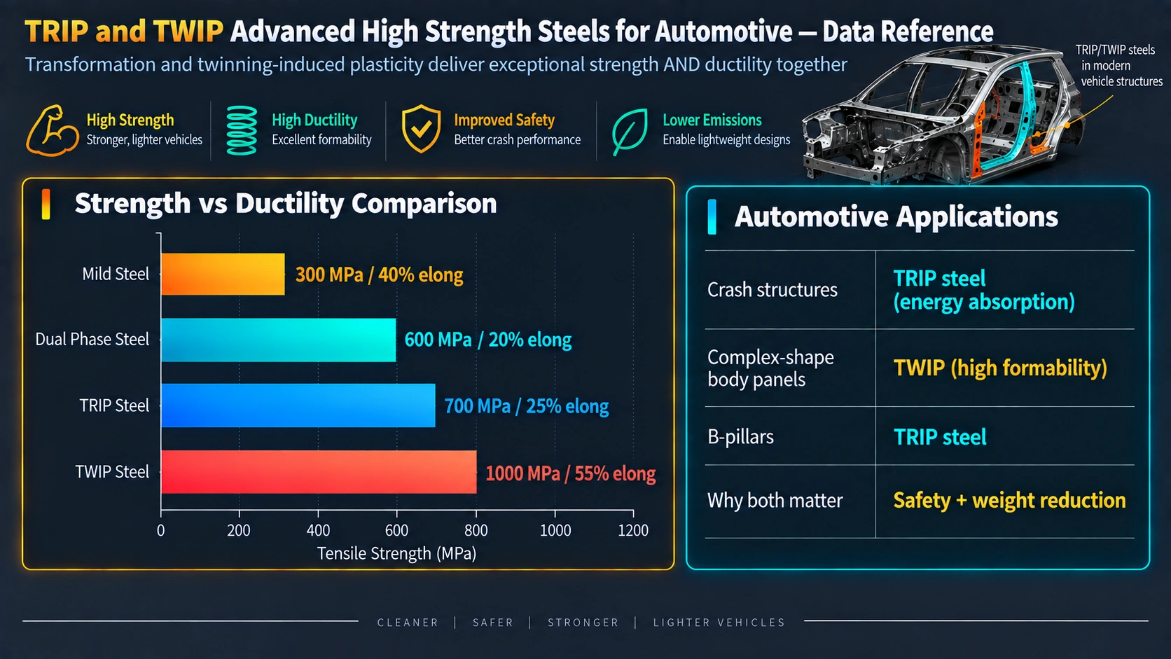
TRIP steels show a higher n-value (strain hardening exponent) than dual-phase steels of equivalent tensile strength, particularly in the range of strain relevant to stretch forming. The progressive TRIP hardening effect delays the onset of necking (as described by the Considère criterion: necking begins when dσ/dε < σ) to significantly higher strains than equivalent-strength conventional steels. This translates to superior stretch formability (higher LDR in deep drawing and higher dome height in Erichsen tests). However, the transformation of austenite to martensite during forming produces a localised volume expansion (ΔV/V ≈ +2–4%) that generates residual compressive stresses in the transformed zones, providing a degree of springback compensation not seen in dual-phase grades.
The progressive hardening also means that TRIP steels work-harden rapidly in crash deformation, providing more energy absorption per unit mass than high-yield-strength grades with lower elongation. The energy absorption capability is characterised by the area under the true stress-strain curve, which for TRIP 780 is typically 1.8–2.2 times that of conventional HSLA at equivalent yield strength.
Forming Characteristics of TWIP Steels
TWIP steels offer forming limit diagrams (FLDs) far superior to any first-generation AHSS grade. Forming limit strains (ε1 at ε2 = 0, plane-strain) of 0.40–0.60 have been reported, compared to 0.15–0.25 for DP 780. The combination of high uniform elongation and high work hardening rate eliminates necking as a forming failure mode across a wide range of strain states. Deep drawing ratios (LDR) exceeding 2.5 are achievable. These characteristics would, in principle, allow the production of automotive body panels and structural components with complex geometry from a single stamping operation, eliminating blanking and sub-assembly steps.
In practice, the forming behaviour of TWIP steels is complicated by two phenomena. First, austenitic TWIP grades show strong planar anisotropy (r-value variation with rolling direction) due to the {110}<112> and {111}<112> deformation textures that develop during cold rolling, producing a pronounced earing tendency in deep drawing. Second, the high Mn content makes TWIP steels significantly more susceptible to delayed fracture (hydrogen embrittlement after forming) than conventional steels, driven by hydrogen trapping at twin boundaries and dislocations — a critical safety consideration for structural automotive components.
Automotive Applications
TRIP steels are currently in mass production for automotive applications including B-pillars, door intrusion beams, bumper reinforcements, longitudinal crash structures (front rails), sill reinforcements, and floor crossmembers. Their advantage over first-generation dual-phase steels is greatest in components that require both formability (complex geometry) and energy absorption in crash (high work hardening). Grades TRIP 600, 700, and 800 are specified in major OEM materials databases (BMW AA, VW TL, Ford WSS-M, USCAR/AHSS Application Guidelines).
TWIP steel adoption in production vehicles has been limited. However, grade X-IP 1000 (formerly Arcelor, now Tata Steel) has been used in select high-performance and motorsport body structures. The high strength-ductility product makes TWIP materials attractive for roof bows, A-pillars in pillar-less door designs, and ultra-thin rollformed sections where the geometry complexity demands high elongation simultaneously with structural performance. Material traceability requirements for AHSS components in safety-critical automotive structures follow similar documentation protocols as described in the material traceability and certification guide.
Weldability of TRIP and TWIP Steels
Resistance spot welding (RSW) is the dominant joining process in automotive body-in-white manufacture. TRIP steels are generally weldable with standard RSW practice but require attention to electrode force, current, and weld time settings because the higher carbon equivalent compared to mild steel creates a harder weld nugget with increased susceptibility to heat-affected zone softening and delayed cracking at elevated carbon levels. The carbon equivalent formula used for weldability assessment is:
CE = C + Mn/6 + (Cr+Mo+V)/5 + (Ni+Cu)/15
For TRIP 800 (C 0.23, Mn 1.7, Si 0.4, Al 1.5), CE ≈ 0.51, which places it at the upper limit of good weldability for RSW and requires careful nugget cooling control to avoid martensite cracking in the weld nugget.
TWIP steel RSW is significantly more challenging. The high Mn content increases solidification cracking susceptibility through liquid film formation at grain boundaries during cooling. Excessive weld current produces grain boundary liquation of Mn-rich phases. Laser beam welding (LBW) with rapid cooling can mitigate solidification cracking but produces a very hard martensitic weld metal due to the elevated SFE of the weld pool producing ε-martensite on rapid solidification. Research into friction stir welding (FSW) of TWIP grades has shown promise for applications where solid-state joining is feasible.
For hydrogen-related cracking risks in AHSS welding — particularly relevant to medium-Mn and TWIP grades — the mechanisms described in the hydrogen-induced cracking guide apply directly, with Mn-rich austenite acting as a strong hydrogen trap site.
Production Challenges and Current Research Directions
TWIP Steel Production Barriers
The high Mn content of TWIP steels creates challenges at every stage of production. During melting, Mn vaporisation at steelmaking temperatures causes furnace refractory attack and requires closed-furnace or vacuum induction practice. Mn segregation during solidification of continuously cast slabs creates compositional banding that persists through rolling and can cause position-dependent SFE variation across the strip width. Hot rolling requires higher mill forces due to the elevated strength of the austenitic matrix at rolling temperatures. The Mn oxide surface layer impairs descaling efficiency and downstream zinc adhesion for galvanised products.
Delayed Fracture (Hydrogen Embrittlement)
Delayed fracture in high-strength steels refers to the time-delayed cracking that occurs hours to weeks after forming, driven by hydrogen absorbed during pickling, phosphating, or electrocoating. For TRIP and TWIP steels, hydrogen trapping at austenite-martensite interfaces (TRIP) and at deformation twin boundaries (TWIP) is significantly higher than in ferrite or martensite, making these grades more susceptible at equivalent strength levels. The trapped hydrogen lowers the critical stress intensity for crack propagation, enabling sub-critical crack growth. Mitigation strategies under investigation include bake hardening treatment (150–200°C, 20 min) to degas hydrogen after forming, Al-free TWIP compositions with reduced trapping density, and surface coatings that reduce hydrogen entry during processing.
Medium-Manganese Lüders Band Suppression
The pronounced yield point phenomenon in medium-Mn steels, driven by Mn-C atmosphere pinning of dislocations at austenite-ferrite interfaces, produces macroscopic Lüders bands during tensile deformation. In automotive stamping, these bands appear as surface stretchmarks or “orange peel” that are unacceptable on visible panels. Strategies to suppress Lüders bands include micro-alloying additions (Ti, Nb, V) to pin dislocations through precipitate strengthening, pre-straining before stamping, and compositional adjustments to reduce the yield point extension below the strain levels encountered in forming. Understanding the grain boundary effects on Lüders band formation relates directly to the fundamental principles covered in the grain boundaries and segregation article.
Computational Alloy Design
CALPHAD-based thermodynamic modelling using commercial databases (Thermo-Calc TCFE, Pandat) is now routinely applied to predict SFE, Ms temperature, and phase fractions as a function of composition in TRIP and TWIP alloy design. First-principles density functional theory (DFT) calculations have improved the fundamental understanding of SFE dependence on alloying element interactions. Phase-field modelling of austenite decomposition kinetics during the bainitic hold in TRIP processing allows virtual optimisation of the two-stage thermal cycle without physical trials. Machine learning models trained on accumulated AHSS composition-processing-property datasets are increasingly accurate in predicting the retained austenite fraction and mechanical properties of new alloy compositions, reducing development cycle times significantly.
Frequently Asked Questions
What does TRIP stand for in TRIP steel?
What is stacking fault energy and why does it control TRIP vs TWIP behaviour?
What is the typical microstructure of a TRIP-assisted multiphase steel?
What is the Mn content of TWIP steels and why is it so high?
How does the TWIP hardening mechanism differ from conventional work hardening?
What are the key differences between first-generation and third-generation AHSS?
What is the Olson-Cohen model and how does it apply to TRIP steels?
Why are TWIP steels not yet in widespread mass production?
What role does silicon play in TRIP-assisted multiphase steels?
Recommended Reference Books
Steels: Microstructure & Properties — Bhadeshia & Honeycombe (4th Ed.)
Definitive graduate-level text covering all steel microstructures including TRIP, TWIP, bainite, martensite, and advanced high-strength grades.
View on AmazonAdvanced High Strength Steel — SpringerBriefs
Modern reference on AHSS processing, microstructure, mechanical testing, and automotive forming applications including TRIP and TWIP grades.
View on AmazonPhysical Metallurgy — Cahn & Haasen (4th Ed., 3 vols.)
Comprehensive physical metallurgy reference covering stacking fault energy, deformation mechanisms, phase transformations, and austenite stability in depth.
View on AmazonFundamentals of Metal Forming — Hosford & Caddell
Rigorous treatment of sheet metal forming mechanics, forming limit diagrams, work hardening exponents, and material selection for press-forming applications.
View on AmazonDisclosure: MetallurgyZone participates in the Amazon Associates programme. If you purchase through these links, we may earn a small commission at no extra cost to you. This helps support free technical content on this site.
Further Reading
