52100 Bearing Steel (100Cr6 / SUJ2): Metallurgy, Heat Treatment, and Carbide Control
AISI 52100 — designated 100Cr6 in the European EN ISO 683-17 standard and SUJ2 in JIS G4805 — is the dominant through-hardening bearing steel worldwide, accounting for well over 80% of all rolling-element bearing production. Its success rests on a precise balance between carbon and chromium that produces a dense population of hard carbides in a martensitic matrix, delivering rolling contact fatigue (RCF) life, dimensional stability, and tribological performance that no other low-alloy steel has matched at its cost. This article examines the compositional design philosophy, microstructural evolution during heat treatment, the critical role of carbide network control, retained austenite management including cryogenic treatment, and the failure modes that governs bearing life.
Key Takeaways
- AISI 52100 (100Cr6/SUJ2) contains nominally 1.0 wt% C and 1.5 wt% Cr; these elements produce (Fe,Cr)3C carbides that resist dissolution and provide hardness after quenching.
- The standard austenitising window is 840–860°C; exceeding this dissolves too many carbides, elevating retained austenite and coarsening austenite grain size.
- Retained austenite must be controlled to <8 vol% per ISO 683-17; excess RA causes dimensional instability under cyclic contact stress.
- Cryogenic sub-zero treatment (−80 to −196°C) reduces retained austenite to <4% and precipitates fine η-carbides that increase hardness and wear resistance.
- Carbide network continuity (rated 1–4) is the primary cleanliness criterion; a continuous network (rating 3–4) drastically reduces L10 fatigue life.
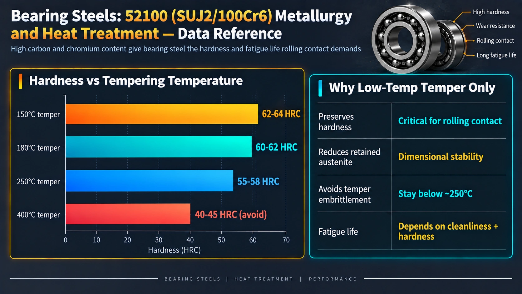
- Final tempered hardness target is 60–64 HRC after tempering at 150–175°C; higher-temperature stabilising tempers (200–250°C) are used for precision or elevated-temperature applications.
Composition Design and Alloying Element Functions
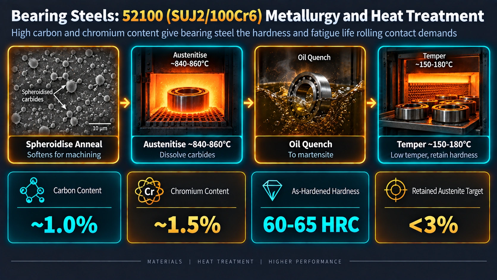
The nominal composition of AISI 52100 appears deceptively simple, yet every element is present within a carefully controlled tolerance that profoundly affects processability, microstructure, and service performance.
| Element | Min. | Max. | Typical | Primary Function |
|---|---|---|---|---|
| Carbon (C) | 0.98 | 1.10 | 1.00 | Forms carbides; controls martensite hardness and carbide volume fraction |
| Chromium (Cr) | 1.30 | 1.60 | 1.45 | Carbide stability; hardenability; temper resistance |
| Manganese (Mn) | 0.25 | 0.45 | 0.35 | Hardenability; deoxidation during steelmaking |
| Silicon (Si) | 0.15 | 0.35 | 0.25 | Deoxidation; solid-solution strengthening of ferrite |
| Phosphorus (P) | — | 0.025 | <0.015 | Residual — segregates to grain boundaries, reduces toughness |
| Sulphur (S) | — | 0.015 | <0.008 | Residual — forms MnS inclusions; strictly controlled in bearing grades |
Role of Carbon
At 1.0 wt%, carbon in 52100 is substantially above the eutectoid composition (0.77 wt%), placing the steel in the hypereutectoid regime. This excess carbon forms primary carbides that persist into the austenitised condition and survive into the final hardened microstructure as discrete globular particles. The volume fraction of carbides in the spheroidised condition is approximately 7–9 vol%. Carbon dissolved in martensite is the primary source of hardness: the martensite hardness of 52100 immediately after quenching (before tempering) reaches 67–68 HRC, dropping to 62–64 HRC after the standard low temper at 160°C.
Role of Chromium
Chromium partitions preferentially into the M3C carbide phase, forming a mixed (Fe,Cr)3C carbide that is harder (~1600 HV versus ~800 HV for Fe3C), more thermally stable, and less soluble in austenite at a given temperature than plain iron carbide. This stability is central to the austenitising strategy for 52100: at 840–860°C, (Fe,Cr)3C particles dissolve only partially, leaving a residual population (approximately 4–5 vol%) that pins austenite grain boundaries and prevents grain coarsening. The dissolved chromium also enhances hardenability through its effect on the C-curve of the TTT diagram, shifting pearlite and bainite formation to longer times and enabling through-hardening of rings up to ~25 mm wall thickness by oil quenching.
Manganese, Silicon, and Residual Elements
Manganese contributes modest hardenability and acts as a deoxidiser during steelmaking. Its upper limit (0.45 wt%) is controlled because excess Mn raises the retained austenite level after quenching by depressing the martensite start temperature (Ms). Silicon is principally a deoxidiser and solid-solution strengthener of the ferritic matrix in the annealed condition. Phosphorus and sulphur are controlled to the lowest practical levels in bearing-grade 52100 because sulphide and phosphide inclusions initiate subsurface fatigue cracks under Hertzian contact stress. Vacuum degassing (VD) or vacuum arc remelting (VAR) routes are used for premium bearing grades to achieve sulphur levels <0.005 wt% and oxygen levels <15 ppm.
Microstructural Conditions: From Cast to Finished Part
As-Cast and Rolled Condition
Continuous cast or ingot-cast 52100 solidifies with a cored microstructure containing carbide networks at prior austenite grain boundaries and along dendrite boundaries. The as-cast carbide morphology includes coarse, angular, and interconnected M3C films that are detrimental to both machinability and subsequent fatigue performance. Hot rolling and forging at 1100–1200°C break down the as-cast structure, but if the finishing temperature falls too low or the cooling rate after rolling is insufficient, carbide networks re-precipitate from austenite on grain boundaries during cooling through the two-phase (γ + carbide) field.
Carbide Network Control
Carbide network continuity is assessed metallographically and rated on a 1–4 scale per SEP 1520 (German steel standard) or equivalent: rating 1 indicates isolated carbide particles; rating 4 indicates a nearly continuous grain-boundary film. The specification for bearing-grade 52100 typically permits a maximum network rating of 2.5. A continuous carbide network functions as a pre-existing crack path under rolling contact loading: fatigue cracks initiate at film junctions and propagate along the brittle carbide film with far lower energy than through the martensitic matrix, drastically reducing L10 life.
Network formation is suppressed in rolling mills by: (a) maintaining a sufficiently high finishing temperature (>850°C) so that the steel passes through the purely austenitic field before coiling or air cooling; (b) fast cooling after rolling to pass through the carbide precipitation range rapidly; or (c) isothermal holding at 700–730°C to transform all residual austenite to pearlite before carbide networks can form. Where networks are present in feedstock, a full spheroidising anneal effectively breaks them up by an Ostwald ripening mechanism.
Spheroidising Annealing (SA Condition)
Bearing steel is supplied in the spheroidised annealed (SA) condition, with all carbide as discrete globular particles (diameter ~0.5–2 μm) in a ferritic matrix. The SA condition provides: hardness of 179–217 HB (ASTM A295 requirement), excellent machinability for turning and grinding of bearing rings, and a uniform starting carbide distribution for the hardening heat treatment. Spheroidising is achieved by prolonged subcritical annealing at 760–790°C (just below A1) for 6–20 hours, or by cycling above and below A1 to repeatedly nucleate new carbide on the ferrite-austenite interface, producing a finer spheroid distribution faster than purely subcritical annealing.
Hardening Heat Treatment
Austenitising
The hardening cycle for 52100 begins with heating to 840–860°C and holding for 20–40 minutes per 25 mm of cross-section. At this temperature the steel is in the austenite + carbide two-phase field (see Figure 1): approximately 0.75–0.80 wt% C and ~0.8 wt% Cr dissolve into austenite, while the balance of carbides remains undissolved. The undissolved carbide population serves three functions: grain boundary pinning (limiting austenite grain size to ASTM grain size number 10–11, ~10 μm); providing a hard wear-resistant phase in the final microstructure; and reducing the carbon and chromium content of the austenite to a level that keeps retained austenite after quenching within acceptable limits.
Exceeding the austenitising temperature increases carbide dissolution and enriches austenite in C and Cr, which depresses both the Ms and Mf temperatures. The consequence is a marked rise in retained austenite after quenching, coarsening of the austenite grain, and reduced fatigue performance. The effect is quantified in Table 2.
| Austenitising Temp. (°C) | Undissolved Carbide (vol%) | C in Austenite (wt%) | Retained Austenite RA (%) | As-Quenched Hardness (HRC) |
|---|---|---|---|---|
| 800 | 8.5 | 0.60 | 3–5 | 61–62 |
| 830 | 6.0 | 0.72 | 7–9 | 64–65 |
| 845 (standard) | 4.5 | 0.78 | 10–12 | 66–67 |
| 860 | 3.5 | 0.83 | 13–16 | 67–68 |
| 900 | 1.5 | 0.92 | 22–27 | 67–68 |
| 950 | <1.0 | 1.00 | 35–45 | 64–66* |
* Apparent hardness reduction at 950°C austenitising despite full carbide dissolution is due to the high retained austenite volume fraction masking the martensite hardness. Source: Derived from data in Stickels (1984), Johnson & Campbell (1969).
Quenching
52100 is quenched from the austenitising temperature into agitated oil at 50–80°C (conventional oil quench) or into a hot oil / marquench bath at 120–180°C for large rings to reduce distortion. The martensite start temperature (Ms) for standard 52100 austenitised at 845°C is approximately 215°C; the martensite finish temperature (Mf) is ~-50°C. This means that a room-temperature oil quench transforms the austenite to approximately 90–93% martensite, leaving 7–12% retained austenite (RA) depending on austenitising temperature and exact composition.
For through-hardening, 52100 requires a minimum cross-section of the bearing ring to be hardened through by the chosen quench medium. The Jominy end-quench hardenability of 52100 shows a hardness of 64–65 HRC at J1 (1/16 in from the quenched end) falling to 57–60 HRC at J8 (8/16 in), which corresponds to adequate through-hardening for rings up to about 25 mm wall thickness in oil.
Retained Austenite and Cryogenic Sub-Zero Treatment
Because Mf for standard 52100 lies at approximately −50°C, a room-temperature quench leaves an unavoidable retained austenite fraction. ISO 683-17 specifies a maximum of 8 vol% RA in finished bearing components. To meet this, sub-zero treatment is performed immediately after oil quenching and before tempering.
Sub-zero treatment protocols in industrial practice:
- Dry ice / acetone bath (cold treatment): −75 to −80°C for 1–2 hours; reduces RA to ~5–7%.
- Liquid nitrogen (deep cryogenic / DCT): −185 to −196°C for 8–24 hours; reduces RA to <2% and promotes precipitation of fine eta (η)-carbides (Fe2C, ~5–10 nm diameter) within martensite laths. These nano-scale carbides increase hardness by 1–2 HRC and measurably improve wear resistance and fatigue life.
Tempering
After quenching (and sub-zero treatment if used), 52100 is tempered to relieve quenching stresses and improve toughness while maintaining the required hardness. The standard tempering schedule is 150–175°C for a minimum of 2 hours. This produces a tempered martensite microstructure with hardness 60–64 HRC and residual RA typically 5–8% (3–5% after sub-zero treatment). For applications where long-term dimensional stability at elevated temperature is required — precision instrument bearings, turbine bearings operating at 120–200°C — a stabilising temper at 200–250°C for 4–8 hours is applied, accepting a hardness reduction to 58–60 HRC in exchange for further conversion of RA and greater resistance to thermally-driven dimensional change.
Standard 52100 Heat Treatment Cycle (Industrial)

Step 1 — Spheroidise anneal:    760–790°C × 8–16 h → furnace cool to <600°C
Step 2 — Austenitise:           840–860°C × 20–40 min (oil or protective atmosphere)
Step 3 — Quench:                Agitated oil at 60°C (or marquench at 150–180°C)
Step 4 — Sub-zero (optional):  −80°C (dry ice) or −196°C (LN₂) within 60 min of quench
Step 5 — Temper:                150–175°C × 2 h minimum → air cool
Step 6 — Straighten/grind, then stabilising temper if required: 200–250°C × 4 h
Hardness, Mechanical Properties, and Property Targets
The mechanical properties of finished 52100 bearing components are dominated by the hardened-and-tempered condition. The primary functional requirement is a narrow hardness band (60–64 HRC) that provides adequate resistance to plastic deformation under Hertzian contact pressure (typically 1.5–3.5 GPa in radial ball bearings) while retaining sufficient fracture toughness to resist crack propagation from surface and subsurface defects.
| Property | Value | Test Standard |
|---|---|---|
| Hardness | 60–64 HRC | ASTM E18 |
| Ultimate tensile strength | 2200–2450 MPa | ASTM E8 |
| 0.2% Proof stress | ~1900–2100 MPa | ASTM E8 |
| Elongation at fracture | 1–2% | ASTM E8 |
| Fracture toughness KIC | 14–18 MPa·m1/2 | ASTM E399 |
| Charpy CVN (10 mm, room temperature) | 6–12 J | ASTM E23 |
| Density | 7.83 g/cm3 | — |
| Modulus of elasticity | 210 GPa | ASTM E111 |
Martensite Start and Finish Temperatures
The Ms and Mf temperatures of 52100 depend on the austenite composition, which in turn depends on austenitising temperature. For standard 845°C austenitising, empirical relationships give:
Andrews (1965) equation:
  Ms (°C) = 539 − 423×[C] − 30.4×[Mn] − 17.7×[Ni] − 12.1×[Cr] − 7.5×[Mo]

For 52100 (C ≈ 0.78 wt% in solution at 845°C, Mn ≈ 0.35, Cr ≈ 0.80):
  Ms ≈ 539 − (423 × 0.78) − (30.4 × 0.35) − (12.1 × 0.80)
  Ms ≈ 539 − 330 − 11 − 10
  Ms ≈ 208°C

Mf ≈ Ms − 215°C = 208 − 215 ≈ −7°C (approximate; Mf often given as ~−50°C
  in practice due to sluggish kinetics of final martensite formation)
The difference between the calculated Mf (~−7°C) and the practical Mf (~−50°C) reflects the autocatalytic hardening of the untransformed austenite by surrounding martensite, which progressively raises the activation energy for further transformation. This is precisely why sub-zero treatment at −80°C or below is required to reach near-complete martensite transformation.
Rolling Contact Fatigue and Life Prediction
The primary service requirement of a bearing steel is resistance to rolling contact fatigue (RCF). Under cyclic Hertzian contact, the maximum shear stress occurs at a depth below the surface known as the Hertzian depth, which for typical bearing geometry and load is approximately 0.5× the contact half-width — often 50–200 μm below the surface. Fatigue cracks initiate at this depth at stress concentrators: non-metallic inclusions (primarily oxide stringers), carbide clusters, or decarburised surface layers.
L10 Life and the Lundberg-Palmgren Equation
Bearing life is characterised by the L10 life: the number of revolutions that 90% of a population of bearings will complete without material fatigue failure. The Lundberg-Palmgren model, foundational to ISO 281, gives:
L10 = (C / P)^p

Where:
  L10 = basic rating life (millions of revolutions)
  C   = basic dynamic load rating (N) — a catalogue value derived from material and geometry
  P   = equivalent dynamic bearing load (N)
  p   = load-life exponent: 3 for ball bearings, 10/3 for roller bearings

Modified life rating (ISO 281:2007 — aISO factor):
  Lnm = a1 × aISO × L10

Where:
  a1   = life adjustment factor for reliability (a1 = 1 for 90% reliability)
  aISO = combined factor for lubrication film parameter Λ, contamination, and fatigue load limit
The fatigue load limit (Pu) introduced in ISO 281:2007 represents the load below which fatigue life is theoretically infinite — an important distinction for highly loaded bearings. Achieving P/Pu < 1 requires both adequate steel cleanliness and a sufficiently thick elastohydrodynamic lubrication film to prevent metal-to-metal contact (lubrication parameter Λ > 3 preferred).
Effect of Steel Cleanliness on RCF Life
The transition from conventional electric arc furnace (EAF) + ladle furnace (LF) 52100 to VD or VAR grades produces oxygen reductions from ~20–25 ppm to <10 ppm, translating to practical RCF life improvements of 2–5× at equivalent load and lubrication. This is captured in the bearing industry’s shift from the original Lundberg-Palmgren model (which implicitly assumed 1950s-era steelmaking cleanliness) to the ISO 281 modified life that explicitly accounts for material quality through the aISO factor.
Comparison with Alternative Bearing Steel Grades
52100 competes with case-hardening bearing steels (e.g., 8620, 18CrNiMo7-6) for applications where impact loading or thin sections preclude through-hardening. For elevated-temperature or corrosive environments, alternative alloys are used.
| Grade | Designation | Type | Max. Service Temp. (°C) | Hardness (HRC) | Key Advantage | Limitation vs. 52100 |
|---|---|---|---|---|---|---|
| 52100 | 100Cr6 / SUJ2 | Through-hardening | ~120 | 60–64 | Lowest cost; highest RCF life at moderate temperature | — reference grade |
| M50 | — | Secondary hardening tool steel | 315 | 60–62 | Elevated-temperature hardness retention; aerospace | High cost; complex heat treatment |
| M62 | — | Secondary hardening tool steel | 340 | 62–64 | Higher temperature capability than M50 | Very high cost; difficult machining |
| 440C | X105CrMo17 | Martensitic stainless | ~150 | 57–60 | Corrosion resistance in water-contaminated environments | Lower hardness, lower RCF life |
| 8620 (case) | 21NiCrMo2 | Case-hardening | ~120 | 58–62 (case) | Tough core; suitable for impact loading | Lower surface hardness; more complex processing |
| Cronidur 30 | X30CrMoN15-1 | Nitrogen-alloyed stainless | ~200 | 58–62 | Excellent corrosion resistance + good RCF life | Very high cost; limited availability |
International Equivalents and Standards Coverage
AISI 52100 is standardised under ASTM A295 (bars and tubes for bearing applications) and ASTM A485 (high-hardenability 52100 Grade 4, for large cross-sections). ISO 683-17 specifies 100Cr6 and 100CrMnSi6-4 (with added Mn and Si for heavier sections). The following equivalent designations apply:
| Standard | Designation | Key Differences |
|---|---|---|
| AISI/SAE (USA) | 52100 | Reference; ASTM A295 specification |
| EN ISO 683-17 (Europe) | 100Cr6 | S < 0.015%; O < 15–12 ppm (Grade 1–3) |
| DIN (Germany) | 100Cr6 (1.3505) | Essentially identical to EN ISO 683-17 |
| JIS G4805 (Japan) | SUJ2 | C: 0.95–1.10%; Cr: 1.30–1.60% |
| GOST 801 (Russia) | ShKh15 | Slightly broader Cr range (1.30–1.65%) |
| GB/T 18254 (China) | GCr15 | Nearly identical to 100Cr6 |
| BS 970 Part 1 (UK) | 535A99 | Superseded by EN ISO 683-17 |
Surface Finishing and Tribology
The contact fatigue life of 52100 bearings is strongly influenced by the surface condition of raceways and rolling elements. After hardening, components are ground to within ~0.1 mm of final size, then superfinished by abrasive belt, honing stone, or magnetic float polishing to achieve raceway surface roughness Ra < 0.05 μm and ball Ra < 0.010 μm. The ratio of the elastohydrodynamic (EHD) film thickness h to the composite roughness σ of the contact pair defines the lubrication parameter Λ:
Λ (lambda) = h / σ_composite

Where:
  h             = EHD central film thickness (nm to μm; calculated from Hamrock-Dowson)
  σ_composite  = √(Ra₁² + Ra₂²) — combined roughness of race and rolling element surfaces

Λ ≥ 3 : Full film EHD lubrication — no asperity contact; maximum fatigue life
1 ≤ Λ < 3 : Mixed lubrication — partial asperity contact; life reduction factor applies
Λ < 1    : Boundary lubrication — severe asperity contact; fatigue life severely reduced
For a typical grease-lubricated medium-speed bearing at 1500 rpm, h is approximately 100–300 nm. This means achieving Λ > 3 requires Ra < 30–100 nm — readily achieved with superfinished 52100 components but impossible with rough-ground or corroded surfaces. Corrosion pitting (even shallow pitting from hydrogen embrittlement during acid cleaning or electrostatic discharge) creates stress concentrators that drop effective fatigue life by one to two orders of magnitude.
Common Failure Modes in 52100 Bearing Components
Understanding the failure metallurgy of 52100 is critical for root cause analysis of premature bearing failures, which follow the methodology of ASM Handbook Vol. 11.
- Subsurface inclusion-initiated spalling: Most common fatigue mode in clean 52100 under normal loading. Crack initiates at an oxide or sulphide inclusion at the depth of maximum orthogonal shear stress, propagates along crystallographic planes, and ultimately produces a shallow surface spall. Life is predicted by Lundberg-Palmgren model; cleaner steels show longer L10.
- Surface-initiated spalling: Occurs under mixed or boundary lubrication (Λ < 1). Asperity contact produces microcracks at surface defects, corrosion pits, or grinding burns. Distinguished from subsurface spalling by crack morphology (shallower angle, V-shaped in cross-section).
- White etching areas (WEA / WEL): Also called white etching cracks (WEC) or white layer damage. Appear as feathery white-etching regions in metallographic sections. Mechanism involves localised severe deformation, adiabatic shear, or tribochemical reactions that produce nanocrystalline layers (~10–20 nm grain size) highly resistant to chemical etching. WEA are associated with high-speed, high-load, or electrical discharge conditions. See also martensite-like transformation of the surface.
- Plastic deformation (brinelling): Occurs when static or shock load exceeds the yield strength of the martensitic surface. True brinelling produces permanent indentations; false brinelling occurs under fretting vibration in static bearings.
- Hydrogen embrittlement: Nascent hydrogen from lubricant decomposition or electrochemical corrosion diffuses into 52100, reducing fracture toughness from ~15 MPa·m1/2 to <10 MPa·m1/2 and causing premature cracking. Relevant to hydrogen cracking mechanisms in high-strength steels.
- Overheating / thermal softening: Localised flash temperatures at asperity contacts or from interrupted lubrication can reach 300–500°C, transforming retained austenite and softening the tempered martensite. Evidence: discolouration (blue-black oxide), drop in surface hardness, and dimensional changes.
Industrial Applications
52100 bearing steel is used wherever high-cyclic Hertzian contact demands a combination of high hardness, dimensional stability, and cost-effectiveness:
- Deep groove ball bearings (DGBB): The dominant product for 52100. Inner rings, outer rings, and balls for electric motors, pumps, machine tool spindles, and automotive wheel hubs.
- Tapered roller bearings: Rings and rollers for automotive differentials, gear transmissions, and heavy truck wheel ends.
- Cylindrical and spherical roller bearings: Steel mill rolls, paper machine rolls, large electric generators.
- Angular contact ball bearings: Machine tool spindles where axial and radial loads are combined; typical spindle running speed 15,000–60,000 rpm demands the tightest retained austenite control and finest surface finish.
- Needle rollers and caged rollers: Compact high-load applications in transmission systems and helicopter rotor heads (where M50 or M50NiL case-hardened steel may be preferred for elevated-temperature resilience).
Frequently Asked Questions
What is the austenitising temperature for 52100 bearing steel?
Why is retained austenite harmful in bearing components?
What is the role of chromium in 52100 steel?
What does sub-zero (cryogenic) treatment do to 52100?
What is the spheroidised carbide condition and why is it required?
How is carbide network rating assessed and why does it matter?
What tempering temperature is used for finished 52100 bearing rings?
What is the equivalent designation of 52100 in European and Japanese standards?
What surface treatments are applied to 52100 bearing components?
Recommended Reference Texts
Steels: Microstructure and Properties — Bhadeshia & Honeycombe (4th Ed.)
Authoritative graduate-level reference covering all aspects of steel microstructure, phase transformations, and heat treatment including high-carbon and bearing steels.
View on AmazonBearing Design in Machinery — Avraham Harnoy
Comprehensive engineering reference covering bearing selection, load analysis, fatigue life prediction (ISO 281), and materials including 52100 and alternative bearing grades.
View on AmazonASM Handbook Vol. 1: Properties and Selection of Irons, Steels, and High-Performance Alloys
The foundational ASM reference for ferrous alloy composition, properties, and application data including tool steels, bearing steels, and carburising grades.
View on AmazonMaterials Science and Engineering: An Introduction — Callister & Rethwisch (10th Ed.)
Standard undergraduate and postgraduate text covering phase diagrams, heat treatment, mechanical properties, and failure analysis applicable to bearing steel metallurgy.
View on AmazonDisclosure: MetallurgyZone participates in the Amazon Associates programme. If you purchase through these links, we may earn a small commission at no extra cost to you. This helps support free technical content on this site.
Further Reading
Martensite Formation in Steel
Crystallography, driving force, habit planes, and hardness of martensite in low-to-high carbon steels.
Quenching and Tempering
Full heat treatment cycle mechanics from austenitising through quench media selection to tempering response curves.
Iron-Carbon Phase Diagram
Complete guide to the Fe-Fe3C diagram: invariant reactions, phase regions, and engineering interpretation.
Retained Austenite: Causes and Effects
Why austenite is retained after quenching, measurement methods, and its effects on dimensional stability and fatigue.
Annealing and Normalising
Process types, temperature selection, and microstructural outcomes including spheroidising and subcritical annealing.
Steel Hardness Conversion Calculator
Convert between HRC, HV, HB, and HRA scales per ASTM E140-12b with NACE MR0175 compliance check.
Hardness Testing Methods
Rockwell, Vickers, Brinell, Knoop, and Shore hardness test principles, scales, and applicability.
Hydrogen-Induced Cracking
Mechanisms of hydrogen embrittlement in high-strength steels including hydrogen trapping at carbide interfaces.
