Corrosion Allowance and Remaining Life Calculator
Last updated: · Reading time about 10 minutes
A remaining life calculator for corrosion turns ultrasonic thickness readings into a corrosion rate, the corrosion allowance still in hand and the years left before the wall reaches its minimum required thickness. It works from thickness-loss data and the design t-min, so it is a different tool from the corrosion rate weight-loss calculator, and the t-min itself comes from a calculation such as the one in the pressure vessel wall thickness calculator.
Corrosion Allowance and Remaining Life Calculator
- Corrosion rate from thickness data is thickness lost divided by elapsed time.
- Remaining life is the remaining corrosion allowance divided by that rate.
- The higher of the long-term and short-term rates gives the shorter, safer life.
- The next inspection is normally set at no more than half the remaining life, within the code maximum.
- The method assumes uniform corrosion; pitting and localised thinning need a fitness-for-service assessment.
What Are Corrosion Allowance and Remaining Life?
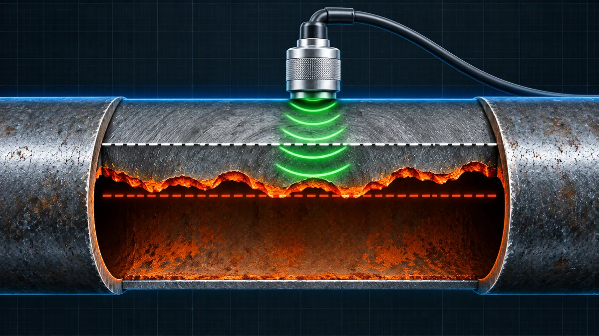
Remaining life is the time until measured wall thickness corrodes down to the required minimum.
Corrosion allowance is the extra wall thickness added at design to cover expected metal loss over the design life. A vessel or pipe is built thicker than the pressure and load calculation requires, and that excess is the allowance. The calculation therefore has two thicknesses at its core: the minimum required thickness t-min, below which the component is not fit to operate, and the actual thickness, measured in service. The gap between them is the corrosion allowance that remains.
Remaining life depends only on how large that remaining allowance is and how fast it is being consumed. Because both come from field measurements, the method is the basis of in-service inspection programmes for pressure vessels, piping and tanks under codes such as API 510 and API 570.
How Is Remaining Life Calculated?
Corrosion rate is calculated from thickness loss over time. Two rates are normally compared: the long-term rate over the whole service history and the short-term rate between the two most recent readings.
The calculation is linear: it assumes the metal loss continues at the chosen rate until it reaches t-min. Where the rate is changing, for example because a coating has failed or the process has changed, the short-term rate is the better guide. Where the thickness reading scatters, a longer baseline smooths it out. The mass-based route to a rate, with weight-loss coupons, is covered by the weight-loss calculator linked earlier.
How Do You Use the Remaining Life Calculator?
Use measured thickness at the same location on each inspection, and take t-min from the governing design calculation. Then:
- Enter the initial thickness and the years in service since it was measured.
- Enter the current measured thickness and the minimum required thickness t-min.
- Optionally enter the previous thickness and the years since that reading to get the short-term rate.
- Choose which rate to use and set the maximum code interval, then press Calculate, or press Enter in any field.
- Read the remaining allowance, remaining life and inspection interval, and press Reset to start again.
The result panel lists both rates, the rate used, remaining corrosion allowance, remaining life and the suggested interval. For other engineering tools, see the Calculators hub, including the fatigue life calculator for cyclic loading on thinned sections.
Worked Example: A Vessel Shell After 15 Years
A shell plate was 12.0 mm thick when new, and the design calculation gives t-min of 8.5 mm. After 15 years the lowest reading is 10.4 mm. Five years ago the same location read 11.0 mm. The code maximum interval is 10 years.
The short-term rate is 12% higher than the long-term rate, which is a sign that corrosion is accelerating. Using the long-term rate alone would give 17.8 years, about two years longer. The conservative choice protects against that optimism.
Which Corrosion Rate Should Govern?
Inspection codes ask the engineer to choose a rate that reflects the expected future behaviour, not simply the average. A practical approach is:
- Use the higher of the long-term and short-term rates when both are available and the process is unchanged.
- Use the short-term rate when service conditions changed, such as a new feed, a higher temperature or a lost lining.
- Use the long-term rate when the short-term interval is brief and the readings are close to the scatter of the instrument.
- Where no thickness history exists, take a rate from similar service and verify it at the next inspection.
A rate that is close to zero within measurement error does not mean the component is immune. It may mean that the readings are too close together in time to resolve the loss. High-temperature service adds scaling mechanisms that are not captured by a simple thickness average, as discussed in the guide to high-temperature oxidation, and galvanic effects at dissimilar-metal joints can create local hot spots; the galvanic corrosion risk estimator helps screen those pairs.
How Is the Next Inspection Date Set?
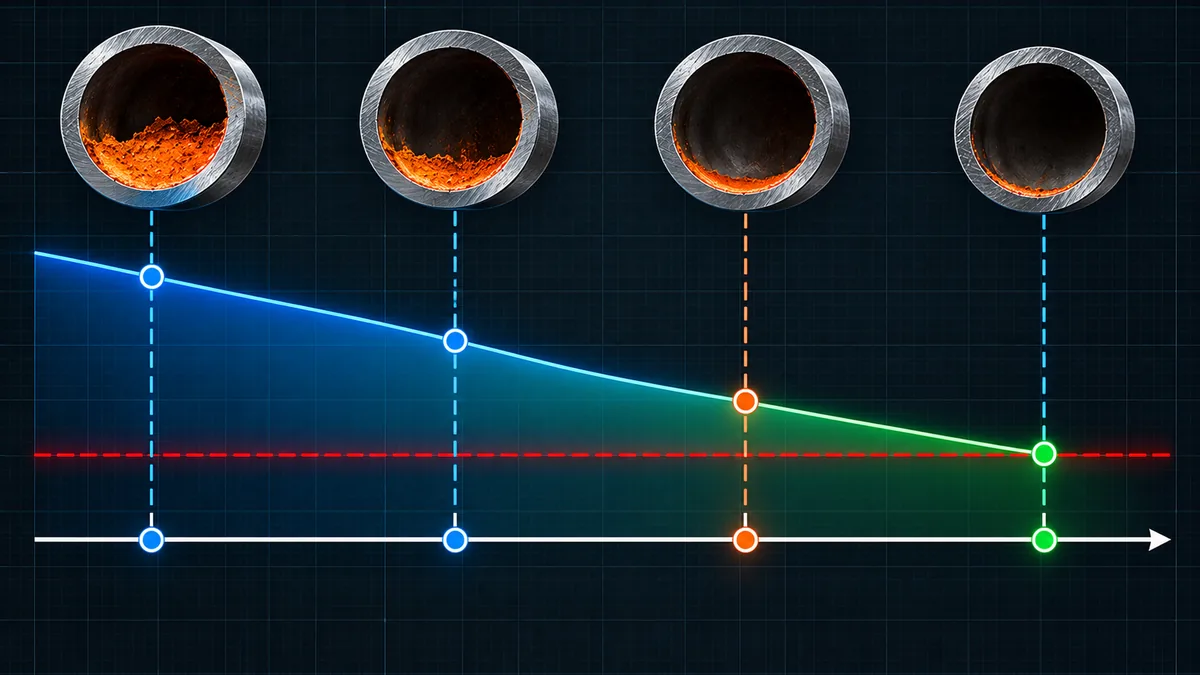
In-service inspection codes commonly set the interval at the lesser of half the remaining life and a fixed maximum for the equipment class. The half-life rule leaves a margin: if the inspection finds a faster rate than expected, there is still allowance in hand to act. When the remaining life is short, the interval shortens automatically, and when the remaining life is very long the fixed cap applies instead. The cap in the calculator is an input because it varies with the code, the equipment and its risk class, and the governing code should be consulted before accepting a result.
If the calculated remaining life is less than the planned operating period, the usual options are to repair or replace the component, reduce the operating pressure so that t-min falls, change the process to slow the corrosion, or increase inspection frequency while the rate is confirmed. Repairs by welding on aged steels need their own care, and the preheat temperature calculator, the carbon equivalent calculator and the weld cooling time calculator cover the preheat and cooling-rate side.
How Accurate Are Thickness Readings?
The arithmetic is exact; the inputs are not. Ultrasonic thickness readings typically have an uncertainty of a few tenths of a millimetre depending on surface condition, temperature, calibration and the operator. Because the corrosion rate is a difference divided by time, a small reading error over a short interval produces a large error in the rate. A 0.2 mm error over a 2-year interval changes the rate by 0.1 mm/year, which is as large as the rate in the worked example.
- Measure at fixed, marked locations so that readings are comparable between inspections.
- Use the minimum of a grid of readings, not a single point, at each location.
- Prefer intervals long enough for the loss to be several times the measurement scatter.
- Record the instrument, probe and calibration block with every reading.
Hardness and toughness of aged material also change local behaviour near thinned areas, so the guide to hardness testing methods and the Charpy impact testing guide are relevant when judging whether a thinned but sound wall is still tough enough for its duty.
When Does the Method Not Apply?
Common mistakes
- Using nominal thickness as measured thickness. Mill under-tolerance means the as-new plate may be thinner than nominal.
- Mixing locations. A rate from two different spots is meaningless.
- Using the wrong t-min. t-min must come from the design calculation for the actual loads and temperature, not from the nominal wall.
- Ignoring corrosion-rate acceleration. A rising short-term rate shortens the true life.
- Extending a short life to avoid action. Where remaining life is shorter than the next run, act before the next inspection.
Range of validity
The method does not cover pitting, grooving, crevice attack, stress corrosion cracking, hydrogen damage or creep. Localised metal loss needs a fitness-for-service assessment such as API 579-1/ASME FFS-1, and pressure-boundary decisions rest on the governing code and a qualified inspector.
Quick Reference
| Quantity | Formula | Unit |
|---|---|---|
| Long-term rate | (t initial – t actual) / years in service | mm/year |
| Short-term rate | (t previous – t actual) / years between readings | mm/year |
| Remaining corrosion allowance | t actual – t min | mm |
| Remaining life | RCA / rate | years |
| Inspection interval | min(remaining life / 2, code maximum) | years |
| mm/year | mils per year (mpy) |
|---|---|
| 0.025 | 1 |
| 0.10 | 3.9 |
| 0.25 | 9.8 |
| 0.50 | 19.7 |
| 1.00 | 39.4 |
Key Terms
- Corrosion allowance
- Extra wall thickness added at design to cover expected metal loss over the design life.
- Minimum required thickness (t-min)
- The thickness below which a component cannot safely carry its design load, from the design or code calculation.
- Corrosion rate
- The thickness lost per unit time, normally in mm/year or mils per year.
- Long-term rate
- The corrosion rate over the whole service history from the initial thickness.
- Short-term rate
- The corrosion rate between the two most recent thickness readings.
- Remaining life
- The time until measured thickness reaches t-min at the chosen corrosion rate.
- Half-life rule
- The practice of setting the next inspection at no more than half the remaining life.
Frequently Asked Questions
How do you calculate remaining life from corrosion rate?
Subtract the minimum required thickness from the current measured thickness to get the remaining corrosion allowance, then divide by the corrosion rate. The result is the time until the wall reaches t-min if the rate stays constant.
What is the difference between long-term and short-term corrosion rate?
The long-term rate uses the initial thickness and the whole time in service. The short-term rate uses the two most recent readings. The short-term rate shows recent behaviour and can reveal acceleration.
Which corrosion rate should be used for remaining life?
The higher of the long-term and short-term rates is the conservative choice when service is unchanged. Use the short-term rate if conditions have changed, and confirm the choice against the governing inspection code.
How often should inspection be done after a remaining life calculation?
Inspection codes commonly set the interval at no more than half the remaining life, and no more than a fixed maximum set by the code and equipment class. The calculator applies the half-life rule and your entered cap.
What is minimum required thickness, t-min?
It is the thickness below which a component can no longer safely carry its design pressure or load. It comes from the design or code calculation using the actual conditions, not from the nominal wall.
Can this method be used for pitting corrosion?
Not reliably. The method assumes uniform loss at a constant rate. Pitting, grooving and other localised damage need a fitness-for-service assessment, such as API 579-1/ASME FFS-1.
What if the corrosion rate is zero or negative?
A zero or negative rate means no measurable loss between readings, which may be real or may be within measurement scatter. The calculator reports no determinable life, and a longer interval or better readings should be used to confirm.
Conclusion
Corrosion allowance and remaining life reduce to two thicknesses and one rate. The remaining allowance is the actual thickness minus t-min, the rate is thickness lost per year, and their ratio is the life left. Choose the rate with care, since the higher of the long-term and short-term values is the safer basis, and cap the inspection interval at half the remaining life or the code maximum. Treat every result as a screening estimate that rests on good readings, a correct t-min and uniform corrosion. For the wider range of corrosion topics and tools, continue to the corrosion science category.
About This Guide
This guide is published by the MetallurgyZone editorial team. The formulae are the standard linear thickness-loss relationships used in in-service inspection practice, and the calculator has been tested against the worked example on this page. It is educational material and does not replace the requirements of the governing code or the judgement of a qualified inspector.
Standards and References
- API 510, Pressure Vessel Inspection Code: In-Service Inspection, Rating, Repair, and Alteration, American Petroleum Institute (api.org).
- API 570, Piping Inspection Code: In-Service Inspection, Rating, Repair, and Alteration of Piping Systems, API.
- API RP 574, Inspection Practices for Piping System Components, API.
- API 579-1/ASME FFS-1, Fitness-For-Service, American Petroleum Institute and ASME (asme.org).
- ASME Boiler and Pressure Vessel Code, Section VIII, Division 1, ASME.
