Grossmann Hardenability Calculator: Ideal Critical Diameter (DI) from Composition
Last updated: · Reading time about 14 minutes
A hardenability calculator for DI turns a steel’s chemical analysis and austenite grain size into a single number: the Grossmann ideal critical diameter. That number tells a heat treater how thick a bar can be before the centre stops hardening, and it lets two steels be ranked before any bar is quenched. DI complements the Jominy end-quench test, which measures hardenability by experiment, and it supplies the steel-side input for the quenchant decisions covered in the complete guide to quenching steel.
DI Calculator: Grossmann Ideal Critical Diameter
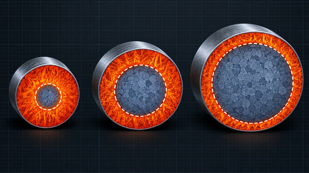
- DI is a property of the steel and its grain size, not of the quenchant.
- DI equals a carbon and grain-size base value multiplied by one factor per alloying element.
- Chromium, molybdenum and manganese raise DI most per weight per cent.
- Real bars harden to a smaller critical diameter D, set by quench severity H.
- Calculated DI is a screening estimate; confirm critical parts with a Jominy test.
What Is the Grossmann Ideal Critical Diameter (DI)?
Ideal critical diameter (DI) is the bar diameter forming 50% martensite at the centre under a perfect quench.
M. A. Grossmann introduced the idea in the 1940s to separate two things that are easily confused: how hard a steel can get and how deep it can get that hard. Depth depends on how quickly the bar cools relative to the time the steel can tolerate before diffusional products form. The ideal critical diameter fixes one side of that comparison. It assumes the surface is cooled instantly to the quenchant temperature, a condition written as H equal to infinity, so that the only limit on the centre is the steel itself.
The 50% martensite criterion is a practical convention. A bar that is 50% martensite at the centre is close to the half-hardness point of the microstructure, which is easy to find on a sectioned and etched specimen. The same logic underlies the reading of a Jominy curve, where the distance to half-hardness marks the hardenability. The article on martensite in steel explains why a fully martensitic structure gives the highest hardness for a given carbon content, and the TTT diagram shows why alloying delays the transformations that would otherwise stop martensite forming at the core.
Hardenability is not hardness. A 0.20% carbon steel can have a large DI through manganese, chromium and molybdenum additions yet only reach modest peak hardness, because the martensite it forms has low carbon content. A plain 0.80% carbon steel reaches very high hardness but has a small DI, so the hard layer is thin. The calculator reports depth capacity, and methods such as the guide to hardness testing methods cover the hardness side.
How Is DI Calculated from Composition?
The ASTM A255 approach treats hardenability as a product. A base value DIbase depends on carbon content and prior austenite grain size. Each alloying element then contributes a dimensionless multiplying factor that is greater than 1 and increases with the element’s concentration. The final DI in inches is the base multiplied by every factor, and the value in millimetres is that number times 25.4.
Because the factors multiply rather than add, alloy elements reinforce each other. A steel with 0.95% chromium and 0.15% molybdenum has a combined factor of about 4.4 from those two elements alone, far more than the sum of their separate effects would suggest. That synergy explains why Cr-Mo and Ni-Cr-Mo steels dominate applications that need through-hardening in thick sections. The base values come from a table interpolated linearly between carbon steps of 0.05%. The interpolation is the same one the calculator uses, and it is a simplification of the original graphical charts.
For a steel where the hardening response matters across the whole length of a bar, not only at the centre, the Jominy hardenability calculator predicts a hardness-versus-distance profile. The DI approach here is narrower and quicker: one number, with the intermediate factors visible so each element’s contribution can be audited. The iron-carbon phase diagram gives the background on how carbon shifts the transformation temperatures.
How Do You Use the DI Calculator?
Use the analysis from a mill certificate or spectrometer report, not the nominal grade range, whenever the actual heat is known. The steps are:
- Enter the carbon content in weight per cent, between 0.05 and 0.90.
- Enter manganese, silicon, nickel, chromium, molybdenum, copper and vanadium in weight per cent, using 0 for absent elements.
- Select the prior austenite grain size as an ASTM number from 6 to 8.
- Press Calculate, or press Enter in any field, to see DI in inches and millimetres.
- Read the factor table to see which element contributes most, then press Reset to start a new case.
The result panel lists the base value, every factor and the product, so an unexpected answer can be traced to a single input. For other tools in the same family, see the Calculators hub.
Worked Example: DI for a 0.30C Chromium-Molybdenum Steel
The example uses the analysis published by Herring in Industrial Heating: 0.30% C, 0.40% Mn, 0.20% Si, 0.15% Ni, 0.95% Cr and 0.15% Mo, with an austenite grain size of ASTM 8. The base value for 0.30% carbon at ASTM 8 is 0.1700 in.
The calculator reproduces this result when the worked-example preset is selected. Chromium contributes the largest single factor (3.05), followed by manganese (2.33) and molybdenum (1.45). Nickel and silicon at these levels add only a few per cent. If chromium were removed, DI would fall to roughly 0.7 in, which shows how a 0.95% addition lifts a thin-section carbon steel into a grade that hardens through a bar over 50 mm in diameter.
How Does Grain Size Change DI?
Austenite grain size enters through the base value. Ferrite and pearlite nucleate preferentially at austenite grain boundaries, so a coarser grain structure has fewer nucleation sites and transforms more slowly on cooling. The effect is strong: for 0.40% carbon the tabulated base value is 0.2300 in at ASTM 6, 0.2130 in at ASTM 7 and 0.1976 in at ASTM 8. Moving from ASTM 8 to ASTM 6 raises DI by about 16% for the same chemistry. The role of boundaries as nucleation sites is covered in the article on grain boundaries in steel.
The practical consequence is that grain size is a lever and a hazard. Overheating during austenitising coarsens the grain and raises DI, which can cause a bar that normally hardens only to a shallow depth to harden deeper, but it also lowers toughness and raises distortion and cracking risk. Fine-grain practice with aluminium or niobium additions does the opposite: it lowers DI slightly while improving toughness. Always take grain size from the ASTM E112 measurement or from the supplier’s specified austenitising practice.
| ASTM grain size | DI (in) | DI (mm) |
|---|---|---|
| 6 (coarser) | 5.06 | 128.5 |
| 7 | 4.68 | 119.0 |
| 8 (finer) | 4.35 | 110.4 |
How Does DI Relate to Quench Severity and the Actual Critical Diameter?
DI describes the steel. The quenchant enters through the Grossmann severity number H, the ratio of the surface heat-transfer coefficient to twice the thermal conductivity of the steel, which is normally quoted relative to still water. Typical values quoted for practice are about 0.25 to 0.4 for still oil, 0.4 to 0.8 for agitated oil, about 1.0 for still water and 1.5 to 2.0 for brine. A perfect quench has an H of infinity, and it is the limit that DI refers to.
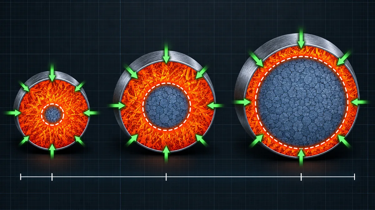
Grossmann charts relate DI, H and the actual critical diameter D. Their key lesson is directional rather than a simple formula: the same steel has a smaller D in a gentler quenchant, and the gap between D and DI narrows as H rises. At low H the quench, not the steel, is the bottleneck, so raising the severity gains more than changing the alloy. At high H the steel is the limit and further agitation gives diminishing returns. Because the D versus DI relationship is read from charts, this calculator reports DI only and does not output D, avoiding a false precision. The cooling mechanics behind H, including vapour blanket, boiling and convection stages, are in the quenching guide linked earlier. Continuous cooling behaviour of the same steel is shown on a CCT diagram.
What DI Values Do Common Steels Have?
The table shows DI calculated for four nominal analyses at ASTM 7. These are typical mid-range compositions used for illustration, so a specific heat will differ. They agree with the broad ranking in the literature: a plain 1045-type steel has a DI below 1 in (25 mm), while 4140-type and 4340-type steels reach several inches.
| Steel type | C | Mn | Si | Ni | Cr | Mo | DI (in) | DI (mm) |
|---|---|---|---|---|---|---|---|---|
| 1045-type | 0.45 | 0.75 | 0.25 | 0 | 0 | 0 | 0.93 | 23.6 |
| 8620-type | 0.20 | 0.80 | 0.25 | 0.55 | 0.50 | 0.20 | 2.60 | 65.9 |
| 4140-type | 0.40 | 0.85 | 0.25 | 0 | 0.95 | 0.20 | 4.68 | 119.0 |
| 4340-type | 0.40 | 0.70 | 0.25 | 1.80 | 0.80 | 0.25 | 6.58 | 167.3 |
The 8620-type result is lower than the 4140-type despite similar alloying, because its core carbon is only 0.20%. Case-hardened components are quenched from carburising temperature with a high-carbon case and a low-carbon core, and the core DI is the number that decides whether the core hardens. This is why carburising grades, covered under case hardening processes, specify a core-carbon and alloy balance, not just case depth.
What Are the Limits of the Multiplying-Factor Method?
Common mistakes
- Confusing DI with D. DI is for an ideal quench. The bar that actually hardens through in oil is smaller.
- Using grade ranges instead of the heat analysis. A 4140 heat at the low end of its manganese and chromium ranges can have a DI far below one at the upper end.
- Ignoring grain size. A single ASTM grain size step changes DI by roughly 8%, as Table 1 shows.
- Applying the method to boron steels. Boron adds a non-linear boost that depends on nitrogen and titanium control.
- Assuming high DI means high hardness. Peak hardness is set by carbon, and tempering then lowers it; see the guide to tempering of steel.
Range of validity
Carbon must lie between 0.05 and 0.90 wt%, grain size between ASTM 6 and 8, and each alloying element within the ranges shown beside the inputs. Larger additions, very different austenitising practice and undissolved carbides in high-carbon tool steels all violate the assumptions. Where the answer decides a design or a specification, run an end-quench test and, for hardness checks on the quenched part, use a standard hardness test.
Quick Reference: Factors and Base Values
| Element | Factor | Factor at 0.5 wt% |
|---|---|---|
| Manganese | 1 + 3.333 Mn (to 1.2%) | 2.67 |
| Silicon | 1 + 0.70 Si | 1.35 |
| Nickel | 1 + 0.363 Ni | 1.18 |
| Chromium | 1 + 2.16 Cr | 2.08 |
| Molybdenum | 1 + 3.00 Mo | 2.50 |
| Copper | 1 + 0.365 Cu | 1.18 |
| Vanadium | 1 + 1.73 V | 1.87 |
| Carbon, wt% | ASTM 6 | ASTM 7 | ASTM 8 |
|---|---|---|---|
| 0.20 | 0.1623 | 0.1509 | 0.1400 |
| 0.30 | 0.1991 | 0.1849 | 0.1700 |
| 0.40 | 0.2300 | 0.2130 | 0.1976 |
| 0.50 | 0.2580 | 0.2380 | 0.2200 |
| 0.60 | 0.2840 | 0.2620 | 0.2410 |
The calculator holds the full table in 0.05% carbon steps from 0.05 to 0.90% and interpolates linearly between entries.
Key Terms
- Hardenability
- The ability of a steel to form martensite to a given depth on quenching, set by composition and grain size rather than by the quench.
- Ideal critical diameter (DI)
- The diameter of a round bar with 50% martensite at the centre after an ideal quench of infinite severity.
- Critical diameter (D)
- The diameter with 50% martensite at the centre for a specific, real quenchant, always smaller than DI.
- Quench severity (H)
- The Grossmann number describing how quickly a quenchant extracts heat from the surface, relative to still water at 1.0.
- Multiplying factor
- A dimensionless number for one alloying element that scales the base DI according to that element’s concentration.
- Prior austenite grain size
- The ASTM grain size number of the austenite present at the start of the quench, which controls nucleation of diffusional products.
- Jominy end-quench test
- The standardised test that measures hardness along a water-quenched bar end to produce a hardenability curve.
Frequently Asked Questions
What is the Grossmann ideal critical diameter (DI)?
DI is the diameter of a round bar that develops 50% martensite at its centre when quenched in a theoretically perfect quench with severity H of infinity. It is calculated from carbon, alloy content and prior austenite grain size, and it ranks steels by hardenability independently of the quenchant.
How accurate is a DI calculated from composition?
The multiplying-factor method is an estimate. It reproduces published examples within a few per cent, but real heats vary with melting practice, segregation, boron and austenitising conditions. Treat the result as a screening value and confirm critical steels with a Jominy test to ISO 642 or ASTM A255.
What is the difference between DI and the actual critical diameter D?
DI assumes an ideal quench. The actual critical diameter D is smaller because real quenchants have finite severity H. Oil, water and brine each give a different D for the same steel, which is why the same bar can harden through in brine but not in still oil.
Why does ASTM grain size change DI?
Coarser austenite grains have fewer grain boundaries, which are the preferred nucleation sites for ferrite and pearlite. Fewer nucleation sites delay diffusional transformation, so a coarser grain (lower ASTM number) raises DI. The penalty is usually lower toughness and a higher risk of quench cracking.
Does the calculator work for boron steels?
No. Boron adds a large but non-linear hardenability boost that depends on nitrogen and titanium control, and it is not covered by the tabulated factors. Results for boron-treated steels would be unreliable, so the calculator does not include a boron input.
What carbon range does the calculator cover?
The tabulated base values span 0.05 to 0.90 wt% carbon and ASTM grain sizes 6, 7 and 8. Inputs outside that range are rejected rather than extrapolated, because the multiplying factors were not validated beyond it.
Can DI predict the hardness of a quenched bar?
Not directly. DI describes how deep martensite forms, not how hard that martensite is. Hardness at full martensite depends mainly on carbon content. To estimate a hardness profile, combine hardenability data with a Jominy curve or a hardness calculation.
Conclusion
The Grossmann ideal critical diameter condenses a steel’s chemistry and grain size into one comparable number. It is built from a carbon and grain-size base value multiplied by a factor for each alloying element, and it assumes a perfect quench, so real bars harden to a smaller critical diameter set by quench severity. Used inside its stated range, DI is a fast way to rank candidate grades, to see which element is doing the work and to judge whether a section size is realistic before a trial quench. It is not a replacement for a Jominy test on critical parts or for the hardness checks that confirm the finished component. For the next step, combine the DI result with transformation data using the tutorial on designing a heat treatment cycle with TTT and Jominy data.
About This Guide
This guide is published by the MetallurgyZone editorial team. Formulae and base values are taken from the sources listed below, and the calculator has been tested against the published worked example. It is educational material and does not replace the requirements of a material specification, customer standard or qualified heat-treatment engineer.
Standards and References
- ASTM A255, Standard Test Methods for Determining Hardenability of Steel, ASTM International (astm.org).
- ASTM A304, Standard Specification for Carbon and Alloy Steel Bars Subject to End-Quench Hardenability Requirements, ASTM International.
- ASTM E112, Standard Test Methods for Determining Average Grain Size, ASTM International.
- ISO 642, Steel: Hardenability test by end quenching (Jominy test), International Organization for Standardization (iso.org).
- ASM Handbook, Volume 4: Heat Treating, ASM International (asminternational.org).
- M. A. Grossmann and E. C. Bain, Principles of Heat Treatment, American Society for Metals, 1964.
- D. S. Herring, Fundamentals of Heat Treating: Ideal Diameter, Industrial Heating, September 2005.
