AWS D1.1 Structural Welding Code: A Complete Overview
AWS D1.1/D1.1M, Structural Welding Code – Steel, is the governing document for most welded steel building and general structural fabrication in North America. This overview walks through its scope, the logic of prequalified versus qualified-by-test welding procedure specifications (WPS), welder qualification, inspection requirements, and the fatigue provisions that separate statically and cyclically loaded connections.
Key Takeaways
- D1.1 applies to steel structures with base metal thickness of 1/8 in (3 mm) or greater; thinner sheet steel falls under D1.3 and bridges under D1.5.
- A prequalified WPS avoids procedure qualification testing only if every essential variable in Clause 5 stays within the prescribed limits.
- Complete joint penetration (CJP) and partial joint penetration (PJP) groove welds are sized differently — PJP welds carry load through a defined effective throat, not the full material thickness.
- The effective throat of a standard 90° equal-leg fillet weld equals 0.707 × leg size.
- Visual inspection is mandatory on every weld; UT, RT, PT, and MT are invoked selectively based on joint type, loading, and thickness.
- Cyclically loaded connections use stress category tables and allowable stress range curves that are markedly more conservative than static design allowables.
1. Scope and Applicability of AWS D1.1
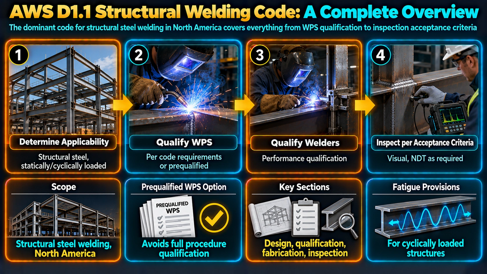
AWS D1.1 governs welding of carbon and low-alloy structural steels in statically and cyclically loaded structures — buildings, towers, platforms, and general fabricated steelwork — using shielded metal arc welding (SMAW), gas metal arc welding (GMAW), flux cored arc welding (FCAW), gas tungsten arc welding (GTAW), submerged arc welding (SAW), electroslag welding (ESW), and electrogas welding (EGW). It does not cover pressure vessels or piping, which fall under ASME Section IX and B31 codes, nor sheet steel below 1/8 in, which is addressed by AWS D1.3-style sheet steel provisions.
1.1 Base Metal and Thickness Range
The code applies to structural steels listed in its base metal tables — typically ASTM A36, A572, A992, A588, and comparable grades — with a minimum thickness of 1/8 in (3 mm). Below that threshold, thin-gauge behaviour (burn-through risk, distortion sensitivity) diverges enough that a separate code, D1.3, applies instead.
1.2 Relationship to Other AWS Structural Codes
| Code | Scope | Typical Application |
|---|---|---|
| D1.1/D1.1M | Structural steel, ≥1/8 in | Buildings, towers, general fabrication |
| D1.5 | Highway bridges | Bridge girders, cross-frames |
| D1.3 | Sheet steel, <1/8 in | Cold-formed steel framing, decking |
| D1.6 | Stainless steel structures | Architectural and corrosion-resistant structures |
| D1.8 | Seismic supplement to D1.1 | Seismic force-resisting systems |
2. Structure of the Code
D1.1 is organized into numbered clauses covering general requirements, design of welded connections, prequalification, procedure and personnel qualification, fabrication, inspection, and specialized processes such as stud welding and strengthening of existing structures, supported by informative and mandatory annexes.
Where the essential logic lives
- Clause 2/3 — design of welded connections, effective areas, and joint details
- Clause 4 — welder, welding operator, and tacker qualification, plus fatigue provisions
- Clause 5 — prequalification of WPS
- Clause 6 — inspection, including NDT acceptance criteria
- Annexes — sample forms, informative commentary, and qualification test details
3. Prequalified Welding Procedure Specifications
A WPS is “prequalified” when every essential variable it specifies falls inside the limits D1.1 has already validated through decades of industry testing — meaning the fabricator can put it into production without running a procedure qualification test. This is the single biggest efficiency lever the code offers a fabrication shop, and it is why welding engineers spend so much time confirming a joint detail is truly prequalified before committing to it.
3.1 Essential Variables for Prequalification
- Welding process — limited to SMAW, GMAW (spray or globular transfer, not short-circuit for prequalification), FCAW, and SAW.
- Base metal group and filler metal classification — matched per the code’s base metal/filler metal tables to ensure compatible mechanical properties and diffusible hydrogen control.
- Joint geometry — groove angle, root opening, and root face must match one of the prequalified joint details (the “B-series” and “TC” joint diagrams).
- Position — flat, horizontal, vertical, or overhead, each with its own heat input and technique constraints.
- Preheat and interpass temperature — minimum values tied to base metal group, thickness, and hydrogen level of the process.
- Heat input range — bounded to control heat-affected zone toughness and avoid excessive grain coarsening; see the related discussion of HAZ microstructure evolution.
3.2 CJP and PJP Prequalified Joints
Prequalified joint details are catalogued by letter-number designation (for example B-U2a for a CJP single-bevel groove weld). CJP grooves are treated, for design purposes, as developing the full strength of the thinner connected part. PJP grooves are sized against the effective throat actually achieved, which is always less than the full material thickness unless backgouging and back-welding are used.
Effective throat, PJP groove (SAW, or GMAW/FCAW with groove ≥ 60°):
    E = depth of groove preparation (no reduction)

Effective throat, PJP groove (SMAW, GTAW, or GMAW/FCAW with groove < 60°):
    E = depth of groove preparation − 1/8 in (3 mm)
4. WPS Qualification by Testing (Clause 4)
When a combination of variables falls outside the prequalified limits — an unlisted base metal, short-circuit GMAW transfer, or an unconventional joint detail — the fabricator must qualify the WPS by test. A test weld is produced under the proposed variables, then destructively and non-destructively evaluated to generate a Procedure Qualification Record (PQR).
4.1 Procedure Qualification Record
The PQR documents the actual variables used during the qualification weld — amperage, voltage, travel speed, preheat, interpass temperature, and the specific consumable lot — alongside the test results obtained. The production WPS is then written to stay within the “essential variable” ranges validated by that PQR; changing an essential variable outside its qualified range invalidates the WPS and requires re-qualification.
4.2 Mechanical Testing Requirements
| Test | Purpose | Typical Criterion |
|---|---|---|
| Reduced-section tension | Confirms joint strength ≥ base metal minimum | Fracture outside weld, or meets specified UTS |
| Side bend / face-root bend | Assesses ductility and fusion, root/toe soundness | No open discontinuity > 1/8 in (3 mm) |
| Macro-etch | Verifies fusion, penetration, and freedom from cracking | Sound fusion at root and sidewalls |
| CVN impact (when specified) | Confirms HAZ and weld metal toughness | Per contract/supplemental requirement |
5. Welder and Welding Operator Qualification
Separately from WPS qualification, each individual welder or welding operator must demonstrate the ability to deposit sound weld metal using a given process, position, and joint type. Qualification is process- and position-specific: passing a flat-position groove weld test does not qualify a welder for overhead fillet welds. D1.1 also requires periodic revalidation — a welder who has not used a qualified process within roughly six months must requalify or provide documented evidence of continued proficiency, since manual dexterity and technique retention degrade with disuse.
6. Statically vs Cyclically Loaded Structures — Fatigue Provisions
D1.1’s Clause 4 fatigue design provisions assign each weld detail to a stress category (commonly labelled A through F, with sub-categories) based on the severity of the geometric stress concentration it introduces — a plain rolled plate edge sits in a mild category, while a transverse stiffener weld toe or an intermittent fillet weld sits in a much more severe one.
Allowable stress range (constant-amplitude fatigue):
    F_SR = (C_f / N)^(1/3)     [category-dependent, N cycles]

where C_f is a category constant and N is the design number of
stress range cycles. Lower stress categories (worse notch severity)
carry a smaller C_f and therefore a lower allowable F_SR for the
same fatigue life.
The practical consequence is that a connection carrying a modest static load may still fail a fatigue check if it is detailed with a severe stress-raiser (an abrupt fillet weld termination, a partial-length backing bar) and subjected to enough load cycles — cranes runways, highway sign structures, and vibrating equipment supports are classic cases where this governs the design.
7. Inspection and NDT Requirements (Clause 6)
Visual testing (VT) is required on every weld, performed both during fabrication (fit-up, root pass) and after completion. Beyond VT, the applicable method depends on joint type, thickness, and load path:
- Penetrant testing (PT) — surface-breaking discontinuities on non-ferromagnetic or fine-grained surfaces where MT is impractical.
- Magnetic particle testing (MT) — surface and near-surface cracks and lack of fusion in ferromagnetic steel; commonly specified for tension-loaded CJP groove weld toes.
- Ultrasonic testing (UT) — the workhorse volumetric method for CJP groove welds in butt, T-, and corner joints subject to tension, per the acceptance-rejection criteria in Clause 6, correlated against reference reflectors.
- Radiographic testing (RT) — used for volumetric evaluation of porosity, slag inclusions, and certain groove weld geometries, subject to film density and radiation-safety controls that keep it far less common than UT for D1.1 fieldwork.
8. Effective Throat and Weld Size Calculations
Fillet weld strength design hinges on the effective throat, not the leg size directly, since load is transferred across the shortest triangular section of deposited weld metal.
Standard 90° equal-leg fillet weld:
    Effective throat, E = 0.707 × leg size (w)

Unequal-leg or non-90° fillet weld:
    E = shortest distance from the root of the joint
        to the theoretical face of the weld

Skewed T-joint (dihedral angle θ, 60° ≤ θ ≤ 135°):
    E = w × sin(θ/2)   [approximate, per applicable table]
Minimum fillet weld size is tied to the thicker part joined (thin base metal cools the weld pool too fast for larger sizes to fuse properly), while maximum size along a plate edge is capped to avoid overlap onto the base metal edge. These interlocking rules are why fillet weld sizing tables are one of the most frequently referenced parts of the code on a shop floor.
9. Industrial Applications and Significance
D1.1 underpins the vast majority of welded steel building frames, industrial platforms, and non-bridge, non-pressure structural steelwork fabricated in North America, and it is frequently adopted by reference in building codes and project specifications worldwide. Its prequalification system lets a certified welding inspector (CWI) and fabricator move from design intent to production weld with predictable, auditable quality, while its qualification-by-test path provides a controlled route for novel joint configurations, exotic base metals, or process combinations the prequalified tables don’t cover. Understanding D1.1 alongside a practical WPS writing exercise is the natural next step for an engineer moving from code theory to a production-ready procedure.
10. Frequently Asked Questions
What is AWS D1.1 and who publishes it?
What thickness range does D1.1 apply to?
What is a prequalified WPS under D1.1?
What is the difference between CJP and PJP groove welds?
How is the effective throat of an equal-leg fillet weld calculated?
What NDT methods does D1.1 require and when?
How does D1.1 treat fatigue-loaded structures differently?
Who is qualified to weld under D1.1?
Recommended Reference Materials
Structural Welding Code Reference Handbooks
Companion references for interpreting prequalified joint tables and essential variables.
View on AmazonWelding Inspection Technology (CWI Prep)
Covers NDT methods, acceptance criteria, and inspection documentation practice.
View on AmazonDesign of Welded Structures
Classic treatment of fillet and groove weld sizing, fatigue categories, and joint design.
View on AmazonWelding Metallurgy Reference Text
Underlying metallurgical basis for heat input, preheat, and HAZ toughness requirements.
View on AmazonDisclosure: MetallurgyZone participates in the Amazon Associates programme. If you purchase through these links, we may earn a small commission at no extra cost to you. This helps support free technical content on this site.
Further Reading
