Rotary Forging Process Guide
Rotary forging, also known as orbital forging, deforms disc-shaped and axisymmetric parts using a nutating die that contacts only a small portion of the workpiece face at any instant, progressively forging the full part over multiple die revolutions at a fraction of the press tonnage conventional flat-die forging would require. This guide extends the general principles covered in the forging metallurgy guide to explain the rotary forging mechanism, its process parameters, and where it fits against conventional forging and related processes for gear blanks, wheel discs, and bearing races.
Key Takeaways
- Rotary (orbital) forging uses a die tilted at a small angle that rotates in a rocking, cone-generating motion, contacting only a wedge-shaped portion of the workpiece face at any instant.
- Because instantaneous contact area is a small fraction of the full part face, required forging force is correspondingly reduced, allowing modest-tonnage presses to forge large-diameter discs.
- Rotary forging is not the same process as rotary swaging, which uses reciprocating radial dies to reduce bar or tube diameter rather than forge a face.
- Like conventional forging, rotary forging produces contour-following grain flow rather than machined-through grain structure, retaining associated strength and fatigue benefits.
- The process is best suited to axisymmetric or near-axisymmetric disc and flange geometries; it is not a general-purpose replacement for closed-die forging of complex shapes.
- Cycle time per part is generally longer than single-stroke conventional press forging because full-face deformation builds up incrementally over multiple die revolutions.
What Is Rotary Forging
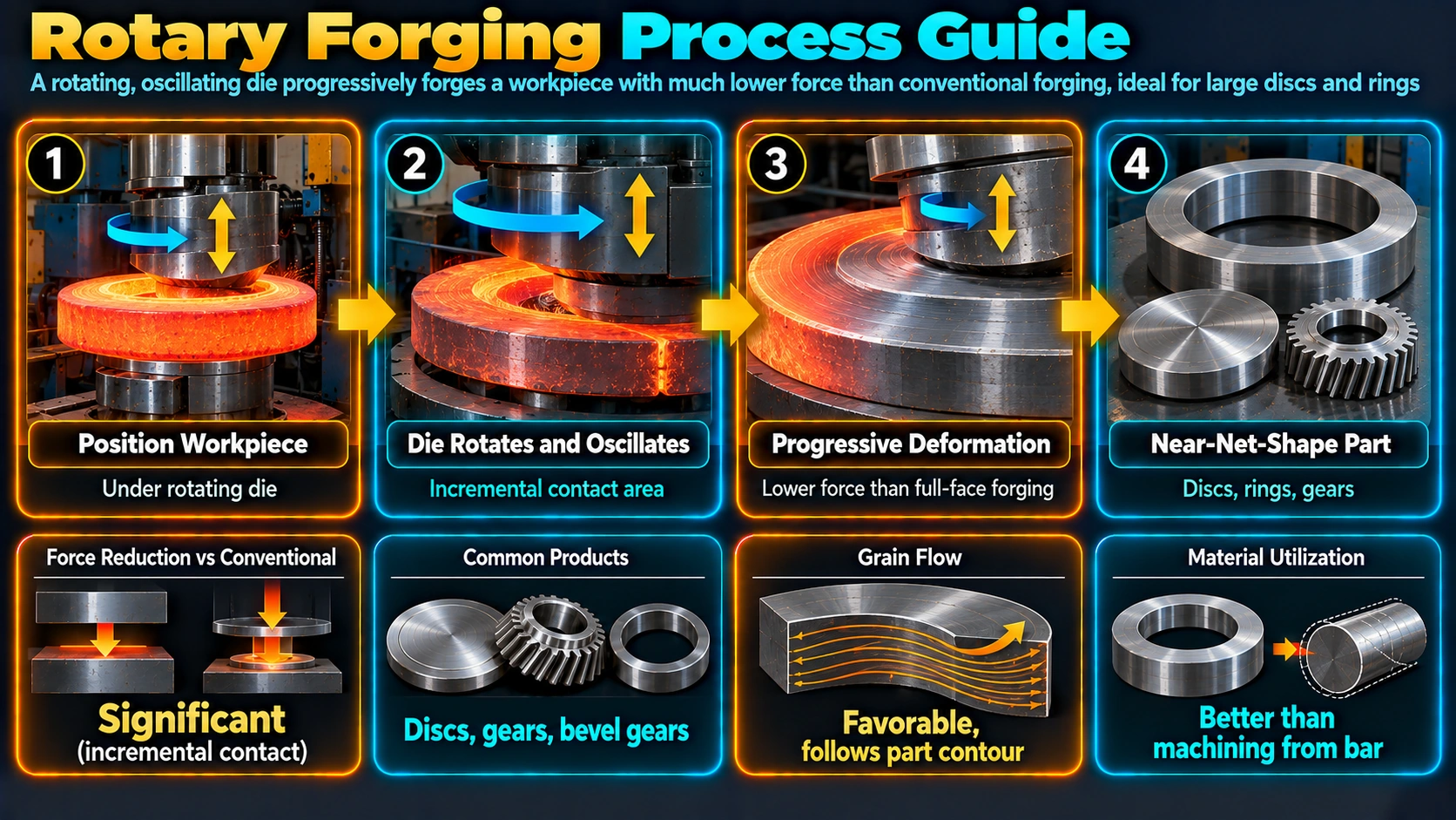
Rotary forging is a specialized incremental forging process for producing disc-shaped and axisymmetric parts with substantially lower instantaneous press force than a conventional single-stroke flat-die operation on the same part diameter would require. The upper die is mounted at a small angle relative to the workpiece axis and driven in a nutating motion, similar to a coin spinning and wobbling on a table, so its point or line of contact continuously traces a path across the die face rather than striking the full face simultaneously.
Rotary Forging vs. Rotary Swaging: An Important Distinction
The term “rotary forging” is sometimes used loosely and can be confused with rotary swaging, a different process that reduces the diameter of round bar, tube, or wire using a set of reciprocating radial dies arranged around the workpiece circumference, driven by a rotating cam or roller ring. Rotary swaging incrementally reduces cross-sectional diameter along the workpiece length, whereas the orbital rotary forging covered in this guide progressively deforms a flat or contoured face, typically reducing axial thickness or forming a shaped disc profile. The two processes serve different part geometries and should not be conflated when specifying tooling or reviewing forging process capability.
Process Mechanism and Force Reduction
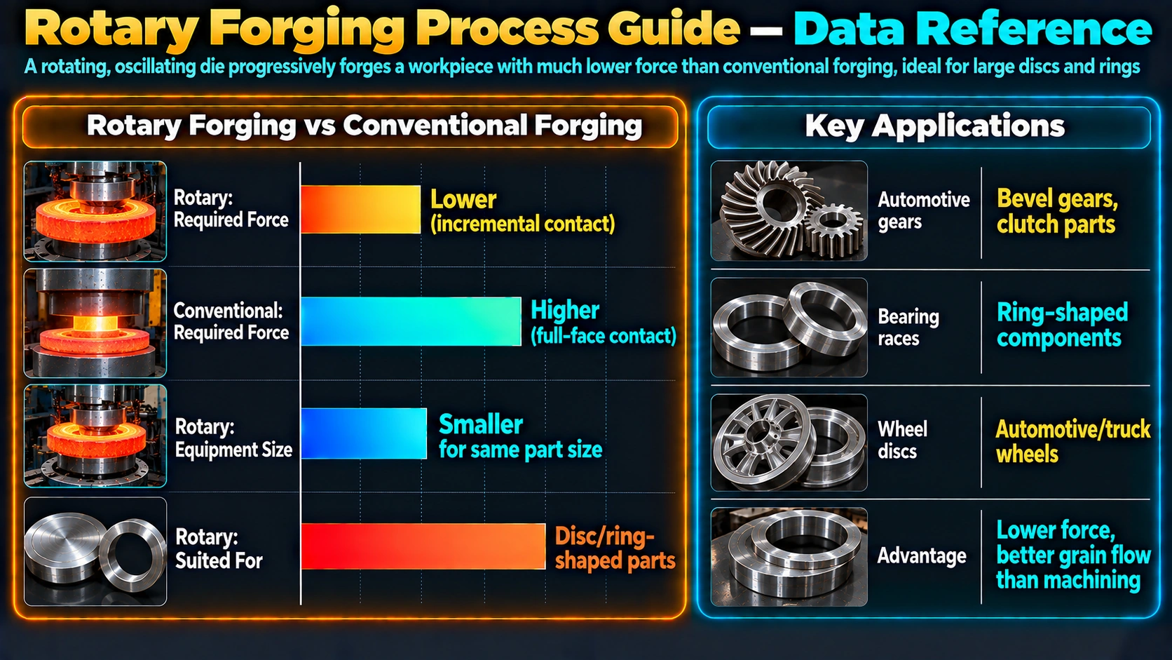
Because the nutating die only loads a small wedge-shaped fraction of the total workpiece face area at any given instant, the peak forging load required is correspondingly a small fraction of what a conventional press would need to deform the same full face in one stroke. This relationship is why rotary forging presses with comparatively modest rated tonnage can produce large-diameter forged discs that would otherwise demand a much larger conventional forging press, making rotary forging attractive for capital-cost-sensitive production of large flat or disc-shaped components.
F_rotary ≈ F_conventional × (A_contact / A_total)

F_rotary       = instantaneous rotary forging load
F_conventional = load a conventional press would need for the full face
A_contact      = instantaneous contact area under the nutating die
A_total        = total workpiece face area being forged

(Illustrative relationship; actual force also depends on material
flow stress, friction, and die geometry at temperature.)
Key Process Parameters
Die Cone Angle
The small angle between the die axis and the workpiece axis controls the size and shape of the instantaneous contact zone; a larger angle generally reduces contact area and instantaneous force further but can increase the number of revolutions needed for full coverage and affect surface finish.
Rotational Speed and Revolutions
The upper die’s nutation rate and the number of revolutions (or indexed rotations of the workpiece) determine total cycle time and the cumulative strain applied at each radial position, since the process builds up full deformation progressively rather than in a single stroke.
Axial Feed Increment
For processes reducing workpiece thickness, an incremental axial feed per revolution advances the die into the workpiece gradually, similar in principle to the incremental material removal logic of a lathe facing operation but applied to plastic deformation rather than cutting.
Forming Temperature
Steel components are most commonly rotary forged hot, in a temperature range broadly similar to conventional hot forging (roughly 1000-1250°C), though warm and cold rotary forging are used for some alloys and part geometries where lower forming force or tighter dimensional tolerance is prioritized over the reduced flow stress benefit of hot working.
Grain Flow and Property Benefits
As with conventional forging, rotary forging plastically deforms the workpiece as a coherent mass rather than removing material, so the resulting grain flow follows the contour of the finished part geometry rather than being interrupted as it would be by machining a shape from bar or plate stock. This contour-following grain structure carries the same directional strength and fatigue-resistance advantages associated with conventional forged parts, discussed further in the forging metallurgy guide, and can be a meaningful factor in fatigue-critical rotating components such as gears and bearing races, complementing surface treatments like those covered in the shot peening guide.
Rotary Forging Compared with Related Processes
| Process | Deformation mode | Typical geometry | Relative press tonnage |
|---|---|---|---|
| Conventional (flat-die) forging | Full-face, single or few strokes | Wide range of shapes | High for large parts |
| Rotary (orbital) forging | Incremental, nutating partial-face contact | Disc / axisymmetric | Low relative to part diameter |
| Rotary swaging | Incremental radial reduction | Bar, tube, wire (diameter reduction) | Low per stroke; many strokes |
| Ring rolling | Continuous rolling between rolls | Ring / annular | Moderate, distributed over rotation |
Advantages and Limitations
Advantages
Rotary forging offers substantially lower press tonnage requirements for a given part diameter than conventional forging, enabling smaller-capital-cost presses to produce large discs; near-net-shape forming that reduces downstream machining; generally lower noise and vibration than hammer forging; and good achievable dimensional accuracy and surface finish for suitable geometries.
Limitations
The process is largely restricted to axisymmetric or near-axisymmetric disc and flange shapes, cycle time per part is typically longer than a single-stroke conventional press operation because full coverage requires multiple die revolutions, and die wear from continuous rolling-type contact plus the more complex nutating die kinematics add tooling and machine control considerations not present in conventional press forging.
Industrial Applications
Rotary forging is widely used for automotive wheel discs, gear blanks, clutch and brake plate components, bearing races, and bevel gear blanks, and is also applied to circular saw blade and other disc-shaped cutting tool blanks where a forged, grain-flow-optimized structure is preferred over a part machined directly from bar or plate stock.
Frequently Asked Questions
What is rotary forging?
How is rotary forging different from rotary swaging?
Why does rotary forging require lower press tonnage than conventional forging?
What shapes of parts are best suited to rotary forging?
Does rotary forging improve grain flow like conventional forging?
What temperature is used for rotary forging steel?
What is the main disadvantage of rotary forging compared to conventional press forging?
What industries commonly use rotary forged components?
Recommended Reference Reading
Forging Handbook (Forging Industry Association)
Comprehensive forging process reference including rotary and orbital forging methods.
View on AmazonMetal Forming: Mechanics and Metallurgy
Broad forming-process reference covering incremental and rotary deformation mechanics.
View on AmazonCold and Hot Forging: Fundamentals and Applications
Process-focused reference on die design and forming force estimation.
View on AmazonPhysical Metallurgy of Steels
Foundational reference on grain flow and forging-related microstructure formation.
View on AmazonDisclosure: MetallurgyZone participates in the Amazon Associates programme. If you purchase through these links, we may earn a small commission at no extra cost to you. This helps support free technical content on this site.
Further Reading
